0
\$\begingroup\$

I need to make a device that can help to build a I-V curve of a diode (both forward and backward) using DAQ. I know how to build them separately, by using series circuit with resistor and diode and get measures with ADC, but how to do this without switches or smth that needs manual control?

I think, H-bridge can handle this. Is there easier and better way? DAQ board have 2 channel DAC (+-10 V, 5 mA), 16 channel digital output 5V, and 16 channel ADC. Thanks.

\$\endgroup\$
6
  • \$\begingroup\$ For reverse bias just use the opposite polarity voltage from the DAC. That's in theory- in practice you may have trouble getting good measurements with a single resistor value. \$\endgroup\$ Commented Dec 21, 2016 at 23:33
  • \$\begingroup\$ What forward and current do you expect? What reverse voltage and current do you need to measure? \$\endgroup\$ Commented Dec 21, 2016 at 23:53
  • \$\begingroup\$ How many orders of magnitude of dynamic range for the current through the diode? Do you need any precision or accuracy? \$\endgroup\$
    – jonk
    Commented Dec 21, 2016 at 23:55
  • \$\begingroup\$ Simplest I can think of is a DAC driving an opamp to drive the diode so that it can run both forward and reverse current into the diode. And then use a low value current sense resistor in series with the diode and a difference amplifier feeding an ADC measuring the voltage across that resistor to measure the current. Need to know voltage sweep range and current measurement range to design to. I can sketch something if interested. \$\endgroup\$ Commented Dec 22, 2016 at 0:26
  • \$\begingroup\$ Thanks everyone for responding. Forgot to say that DAQ also has +12V and +5V sources. Load current should be less than 200mA. Voltage is measured with 0.1 step. Diode is analog of 1N5393. Don't necessary crazy accuracy, just need recognizable curve like in datasheet and close calculated characteristics like built in potential etc. \$\endgroup\$
    – Errainrg
    Commented Dec 22, 2016 at 3:15

2 Answers 2

1
\$\begingroup\$

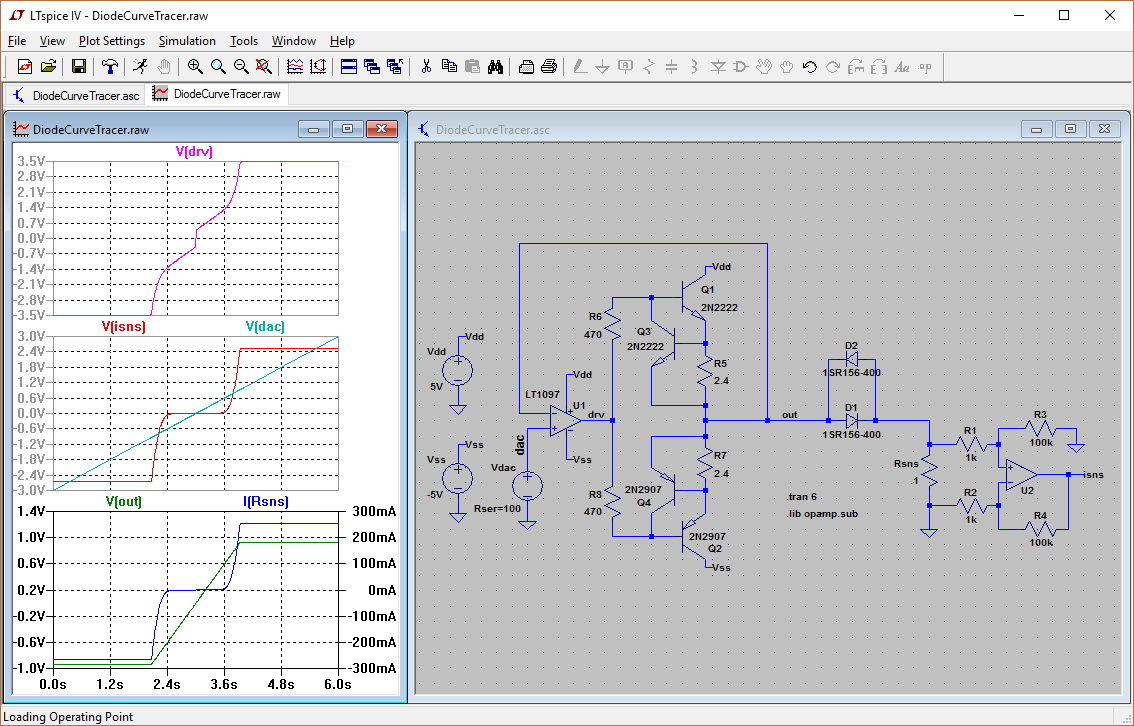
Here's one solution that I mentioned in the comments. It looks complicated but it's not that bad.
enter image description here

Here, your DAC is driving from -3V to +3V to sweep the diode voltage. U1 is basically a simple voltage follower but with Q1 and Q2 tacked on as a power stage. You can use a power opamp, but I decided to make a cheapo design that can use any cheap bipolar opamp. The power stage is some cheap small bipolar transistors. Q1 and Q2 form a simple Class B driver stage. No fancy bias is needed because the opamp will adjust the drive to get the Vout set by the DAC. Plot #1 shows this.

Plot #2 shows the DAC voltage setting versus the detected diode current as an output voltage (0.1 Amp = 1.0 V output).

Plot #3 shows the current limiting in action. Q3 and Q4 act provide current limiting to keep the current no more than about 250 mA. Basically, when current is high enough to make the voltage across R5 reach about 0.6V, Q3 starts to turn on. This in turn shorts across the base-emitter junction of Q1 and prevents Q1 from turning on any further. So you can see that R5 controls the limit value, R5 = 0.6V / (desired Ilimit).

Q4 does the same thing to Q4 so current limiting is symmetrical.

This nice simple current limiter design is from here: http://electronicdesign.com/power/current-limiter-offers-circuit-protection-low-voltage-drop

On the current sensing side, U2 is an opamp wired as a differential amplifier with a gain of 100 (gain = R3 / R1). So if diode current is 100 mA, then you get 0.01V across Rsns, and U2's output is 100x of that or 1.0 Volts, which you can then feed into your ADC. Note that the output voltage swings + or - depending on the direction of the diode current.

Keep in mind, there is a problem with this design: power dissipation can go beyond the rated of the 2N2222 and 2N2907 transistors. At max current of 250 mA, Q1 and Q2 will see about 4 Volts drop, or 4 V x 0.25 Amp = 1 Watt, which well exceeds the 0.6 Watt rating of these transistors. You should use higher power transistors.

Or you can remove the current limiting completely and just stop your sweep in SW when it hits certain current limit.

Anyway, I hope that helps. -Vince

\$\endgroup\$
1
\$\begingroup\$

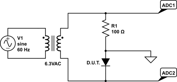
Instead of an H-bridge, just use a wallwart transformer, or triangle wave generator (easy to make, just one data output pin and an op amp) and transformer

schematic

simulate this circuit – Schematic created using CircuitLab

If you make a few dozen simultaneous conversions from ADC1 and ADC2, those give you the current (ADC1 voltage divided by R1) and diode voltage readings for making a scatterplot.

\$\endgroup\$

Your Answer

By clicking “Post Your Answer”, you agree to our terms of service and acknowledge you have read our privacy policy.

Not the answer you're looking for? Browse other questions tagged or ask your own question.