You could always just detect when the room light switch is flipped. I know you already know how to do that much. The light switch, if in the US and semi-modern, will have access to earth ground as well as hot, switched hot (which is connected to neutral through the room light load), and likely neutral too. (Because of the new-fangled devices which may need regular access to hot, neutral, and ground for other reasons.) You could tap in at the ceiling and even be crazy enough to use these cheap $3 Wifi units to act as a web server providing status of your room light. Your auxillary LED light could then just go to that page and monitor the status, using another of the $3 Wifi units. They each need access to +3.3 VDC, though. So it's a bit Rube Goldberg. But robust, at least.
If I really wanted to use an LDR for this, I'd arrange the detector so that it is down deep into a metal tube that points at the room light. I might even bother with a lens or two (I've got boxes of them in nice slip covers.) You can get anodized aluminum optical tubes cheap enough, too. But a black pen barrel might do okay. I have a couple of 3D printers, so I'd probably just whip something up on that. Regardless, I definitely would NOT expose the LDR to the entire room lighting. I'd want to, instead, aim it as accurately as I can at the actual light for the room. A lens and baffling can help, but that may be more trouble than it is worth.
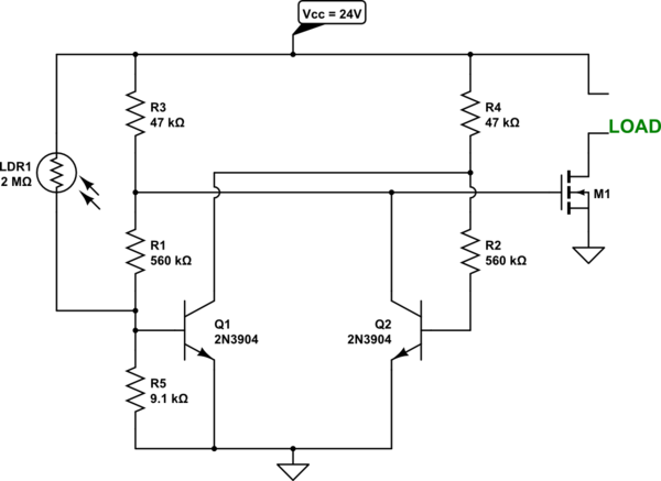
I'd then test the result to see what I get for resistance values with the light ON and OFF and with the tube positioned variously, to account for common miss-alignments that I'd like to tolerate. I'd then design a simple circuit to support an appropriate level of hysteresis based on those values. The following circuit will have two thresholds at about \$300\:\textrm{k}\Omega\$ and \$650\:\textrm{k}\Omega\$, roughly. Which should be good for a typical LDR.

simulate this circuit – Schematic created using CircuitLab
\$R_3\$ and \$R_4\$ are set for the output impedance. I think \$47\:\textrm{k}\Omega\$ is fine for a MOSFET gate drive. Increasing \$R_1\$ and \$R_2\$ will lower the high threshold, reducing the hysteresis. Decreasing them will raise the high threshold. Reducing \$R_5\$ will pull down both thresholds, but the high threshold moves down faster than the low threshold, so reducing it also tights the band, too. That's about it, really.
But you really need to take measurements, first. And that means designing the optics arrangement, too. But a simple, long tube should be fine I think. Pointing that correctly should give you excellent discrimination so that the electronic circuit can do its job, as well.
That's what I'd try, to start.


