2
\$\begingroup\$

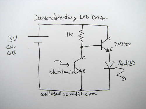
What is the reason for using the transistor (2N3904) is this circuit? What good is this transistor doing in this circuit.What happens if we remove the transistor from this circuit? And what will happen if we use a PNP transistor instead of a NPN transistor.

enter image description here

so my explaination about the original circuit which I implemented because I don't have 50 OHm resistor.When there is light in the room, the circuit inside LDR is complete and hence all the current flows through 1K and LDR branch, and very low current is at base so the amplified current by 2N3904 is insufficient to lightup the LED. When there is dark in the room, the circuit of LDR is open and hence the base current of 2N3904 is maximum (2.3mA) which after amplification is 232.2mA which is sufficient for the LED to work. The LED has voltage drop of 1.8V.

\$\endgroup\$
5
  • 1
    \$\begingroup\$ Re your edit - There's no link between the LDR branch and the LED branch, both are completely independent. So light will change the current in the left branch, but the right one will always see the same current: (3 V - 1.8 V) / 3.22 k\$\Omega\$ = 0.37 mA, which is very low for a LED! (And there's no reason to call me sir, I'm Steven) \$\endgroup\$
    – stevenvh
    Commented Jun 22, 2012 at 9:16
  • \$\begingroup\$ LOL my bad.. Was my explaination about the original circuit correct ? \$\endgroup\$ Commented Jun 22, 2012 at 9:19
  • \$\begingroup\$ Yes, but the 230 mA will most likely destroy the LED. The common collector circuit you've drawn (collector to V+) is not necessarily bad, but here it is because you don't have a resistor in series with the LED, and then a wide variation of \$H_{FE}\$ will cause a wide variation of LED current. At least add a small series resistor, or better use the circuit from my answer. \$\endgroup\$
    – stevenvh
    Commented Jun 22, 2012 at 9:26
  • \$\begingroup\$ Sure. I am going to by apparatus for the circuit you suggested. Thankns \$\endgroup\$ Commented Jun 22, 2012 at 9:35
  • \$\begingroup\$ @Umer - it's important to know whether you are using an LDR or a phototransistor since they are different things. This circuit will not work properly if you are using an LDR unless you alter the resistor value accordingly. Please let us know the part number, the measured resistance across it, or post a picture. \$\endgroup\$
    – Oli Glaser
    Commented Jun 22, 2012 at 14:03

1 Answer 1

4
\$\begingroup\$

The transistor amplifies the current. You have a small current from base to emitter, and the transistor creates a larger current from collector to emitter. The amplification factor can be found as \$H_{FE}\$ in the datasheet, and for small signal transistors is often around 100. So 1 mA base current will result in 101 mA emitter current (that's 100 mA collector current + the 1 mA base current).

I'd like to repeat that this is not the best circuit. There should at least be a small resistor in series with the LED for regulation. If you replace the transistor with another one of the same type you suddenly may have two or three times the LED current. That's because the collector current in your circuit is only determined by base current and \$H_{FE}\$, there's not else limiting it. But for a BC337 \$H_{FE}\$ can vary between 100 and 600! So you can have a 1:6 variation in LED current. That's not good. Do it this way:
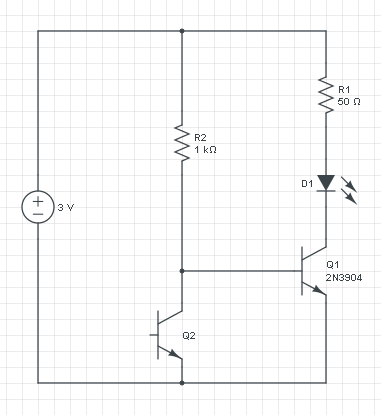
enter image description here

(By the way, drawn in 2 minutes with CircuitLab)

If you leave out Q1 you only have the current through R2 and Q2, and that increases with the light level. So you can't use that directly for the LED, for that you want the current to decrease, and also the current will be too low.

The voltage across R2 is constant: 3 V - 0.7 V = 2.3 V, so it's current will be constant too. The increase/decrease inversion is done by phototransistor Q2: if its current increases the base current to Q1 has to decrease, since the total is constant.

A PNP transistor works like an NPN, but with the currents reversed: a low current from emitter to base will cause a larger current from emitter to collector. If we would replace Q1 with a PNP then the circuit turns upside down:
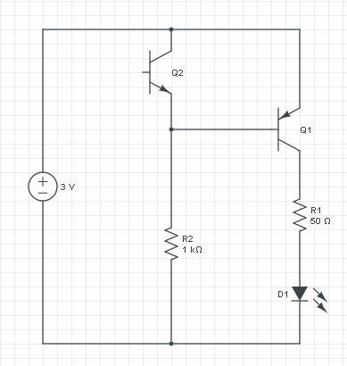
enter image description here

This circuit does exactly what the other does: if it's dark there won't be any current through Q2, and R2 will cause base current in Q1. The current flows from the emitter of Q1 through its base to R2 and ground. That base current will cause a higher collector current which will light the LED. R1 will limit the current to a safe value. If there falls light on Q2 it will cause a higher current through R2, but that current was constant at 2.3 mA ((3 V - 0.7 V) / 1 kΩ), so the base current will decrease, and so will the LED current.
\$\endgroup\$
6
  • 2
    \$\begingroup\$ The circuit is powered by a coin cell, which probably has enough series resistance to omit the series resistor, if you accept a 'throwie-level' quality. \$\endgroup\$ Commented Jun 22, 2012 at 7:26
  • \$\begingroup\$ How did you find the current at collector and at 1K resistor node? \$\endgroup\$ Commented Jun 22, 2012 at 7:37
  • \$\begingroup\$ @Umer - we had 2.3 mA base current: (3 V - 0.7 V) / 1000 \$\Omega\$, that's Ohm's Law. If Q1 has an \$H_{FE}\$ of 100 (you'll find that in the datasheet) the transistor will try to sink 230 mA. But if it drives the collector all down to ground there's 3 V for the LED and R1. If the LED has a voltage drop of 2 V (again, datasheet), that means the remaining 1 V is across the resistor. If the LED needs 20 mA (datasheet!) then Ohm's Law says the resistor should be 1 V / 0.02 A = 50 \$\Omega\$. The transistor will try for 230 mA, but R1 will not allow it. \$\endgroup\$
    – stevenvh
    Commented Jun 22, 2012 at 7:46
  • \$\begingroup\$ @Wouter - Yes, but I don't like to rely on internal resistances. You would use a series resistor for a LED driven by a microcontroller too, even though the FET's resistance will limit the current too. \$\endgroup\$
    – stevenvh
    Commented Jun 22, 2012 at 7:54
  • \$\begingroup\$ Sir see my explaination.. \$\endgroup\$ Commented Jun 22, 2012 at 9:07

Your Answer

By clicking “Post Your Answer”, you agree to our terms of service and acknowledge you have read our privacy policy.

Not the answer you're looking for? Browse other questions tagged or ask your own question.