0
\$\begingroup\$

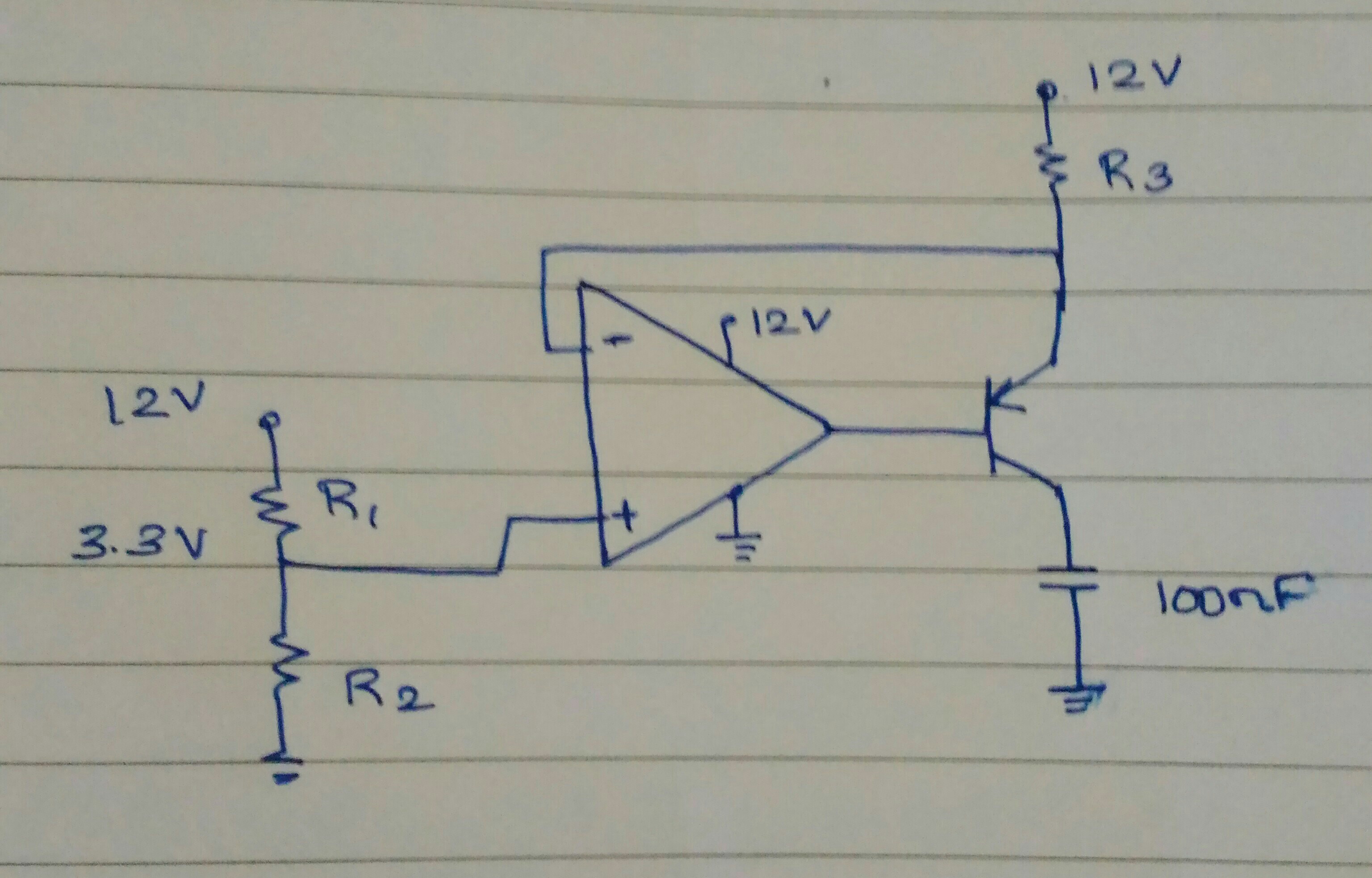
I have the below given circuitry. The circuit provides ( 12 - 3.3 = 8.7 V) 8.7 V / R3 of current.

enter image description here

My specific question: What is the effect of PNP transistor on the variation of current?

Until now I have following cases:

  • more current case: R1 max, R2 min, R3 min

  • min current case: R1 min, R2 max, R3 max

  • supply voltage variation.

Thank you in advance.

Edit: the output is taken across capacitor. The load is not shown which can vary between 1k and 10k.

\$\endgroup\$
6
  • \$\begingroup\$ There's no circuit in the question, so it doesn't make sense. \$\endgroup\$ Commented Jan 1, 2017 at 7:29
  • \$\begingroup\$ @KenShirriff have added now. Had Missed it. \$\endgroup\$
    – User323693
    Commented Jan 1, 2017 at 7:34
  • 3
    \$\begingroup\$ Is this the whole circuit? There's no DC path for the collector current and no obvious source of voltage for R3. \$\endgroup\$
    – Adam Haun
    Commented Jan 1, 2017 at 7:36
  • \$\begingroup\$ @rohat this is the simplest constant current source \$\endgroup\$
    – User323693
    Commented Jan 1, 2017 at 8:28
  • \$\begingroup\$ @Umar Yes, I know. I said that (deleted now) because I couldn't see the load. Anyway, building this with NPN and getting feedback from emitter would be simpler. \$\endgroup\$ Commented Jan 1, 2017 at 8:51

1 Answer 1

2
\$\begingroup\$

One parameter of the transistor that's not corrected by the feedback loop with the op-amp is its alpha, the common-base current gain. You are controlling its emitter current via R3, however the output current is from the collector.

I have a problem working with alpha as I lose count of the 9s. However, as alpha = 1-1/beta, it's almost as easy to work in terms of the beta or hFE.

If the transistor beta changes from 100 to 200, the alpha will change from 0.990 to 0.995, and your output current will increase by 0.5%.

As transistors do have this sort of variation, your sensitivity to transistor variation is similar to your sensitivity to using 1% components for R1, R2 and R3.

As the reference voltage across R3 is directly proportional to the supply voltage (you're not using a reference or regulator here), any change in the supply voltage will give you a directly proportional change in the output current.

\$\endgroup\$
6
  • \$\begingroup\$ Not to correct you but, did you see the 100n cap? How can that circuit work? \$\endgroup\$ Commented Jan 1, 2017 at 7:58
  • \$\begingroup\$ I'm assuming that's a capacitor across the output, I could be wrong of course, no output is shown. \$\endgroup\$
    – Neil_UK
    Commented Jan 1, 2017 at 8:05
  • 1
    \$\begingroup\$ @rohat sorry. The load is not shown. It will be connected across the capacitor. \$\endgroup\$
    – User323693
    Commented Jan 1, 2017 at 8:26
  • \$\begingroup\$ Thank you @Neil will not the opamp do whatever it needs to do in order to generate voltage across capacitor exactly same as its positive input voltage? By varying base current \$\endgroup\$
    – User323693
    Commented Jan 1, 2017 at 10:44
  • \$\begingroup\$ No, the opamp (assuming infinite gain, which is the least approximation here) will do whatever it needs to do to keep the voltage across R3 the same, which nails the emitter current. However, the emitter current splits between base and collector according to the transistor alpha, and that is outside the opamp feedback loop. \$\endgroup\$
    – Neil_UK
    Commented Jan 1, 2017 at 11:11

Your Answer

By clicking “Post Your Answer”, you agree to our terms of service and acknowledge you have read our privacy policy.

Not the answer you're looking for? Browse other questions tagged or ask your own question.