2
\$\begingroup\$

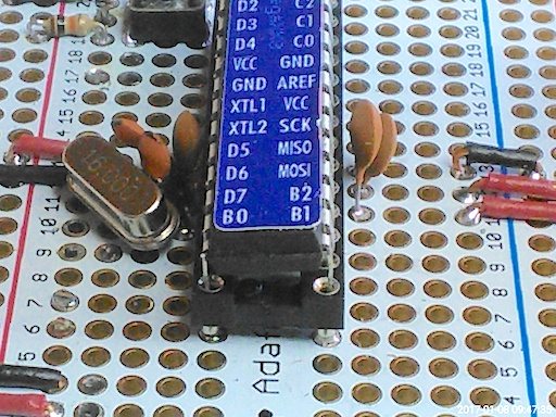
Recently I switched from the leaf-spring type of DIP sockets to the more expensive machined MIL sockets. The leaf-spring type were failing (by the spring parts pulling out of the socket) after a few insertions, or maybe just over time), but the MIL types don't seem to hold the part securely. Notice how this one relaxes into a cockeyed position after having been pressed firmly into the socket:

enter image description here

Are the MIL sockets supposed to be used with some kind of a hold-down? Did I get an atypically bad batch of leaf-spring types, and is there a brand or supplier whose sockets can be counted on?

Update: Isn't the point of socketting to permit removal for replacement or, more frequently, for reprogramming (and if not, then why socket instead soldering the chip directly)? ZIF is a tool for the lab or assembly house, not a part to go on a product. It's bulky, heavy and expensive. Is there no kind of socket that's any better than having to unsolder a part?

\$\endgroup\$
8
  • 1
    \$\begingroup\$ They aren't designed for repeated insertion more than a handful of times. If pushing down firmly so the chip is flat in the holder doesn't hold it, the socket needs replacing. \$\endgroup\$ Commented Jan 8, 2017 at 15:30
  • \$\begingroup\$ Does that apply to either type of socket? Is there some type (besides ZIF, of course) that tolerates repeated insertion? \$\endgroup\$
    – JRobert
    Commented Jan 8, 2017 at 15:32
  • 1
    \$\begingroup\$ The leads on your chip may be incorrectly bent. Could be that way from te start or from past handling especially removal where one side released before the other. What was the source of your sockets? \$\endgroup\$ Commented Jan 8, 2017 at 16:39
  • 1
    \$\begingroup\$ How it is possible the leaf-spring to be "pulled out of the socket" if it usually is a single-piece folded metal, and is soldered to the prototype PCB? \$\endgroup\$ Commented Jan 8, 2017 at 16:40
  • 1
    \$\begingroup\$ @alichen: They break off within the socket and pull out with the chip. They became attached to the pin some way - corrosion, dissimilar metals, ?? \$\endgroup\$
    – JRobert
    Commented Jan 8, 2017 at 17:06

1 Answer 1

4
\$\begingroup\$

If you want to put DIP packages into milled sockets you have to be conscious of the side forces from the package leadframe.
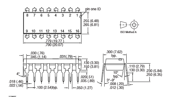
Milled sockets such as you are using are NOT designed to have large side forces on the socket and your DIP package leadframe is bent out at an angle as shown below (typically 5-15 degrees):

enter image description here

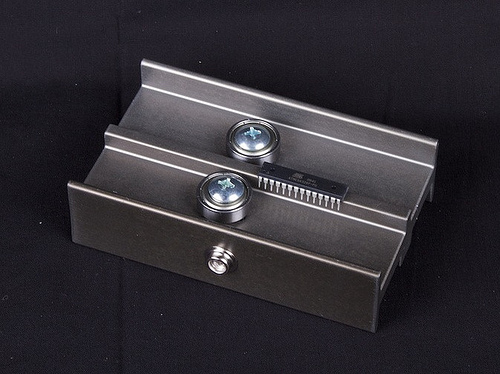
For milled sockets your DIP package should ideally be able to stand with the package lead pins in the center of the sockets without having to put side pressure on the DIP package pins. For hand insertion there are a bunch of creative leadforming jigs (from simple to complex) that will ensure the leads are normal to the body and at the right width:

enter image description here

I usually just hand bend on a flat hard surface. You just have to be careful to bend the leads right at the shoulder and not just bend the lower leg.

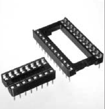
some open frame slide contact IC sockets can actually withstand considerable side force without popping out, but they have a high shoulder to surround the leadframe pins:

enter image description here

...and not designed for continuous re-insertion.

\$\endgroup\$
5
  • \$\begingroup\$ Then why are OFSC sockets any better than soldering the DIP to the board? In a machined socket, if there is no side force, what is meant to secure the chip and make reliable connections? \$\endgroup\$
    – JRobert
    Commented Jan 8, 2017 at 17:21
  • \$\begingroup\$ Machined sockets are either split (they press together) or have Beryllium spring contact sleeves to grip the DIP pin. mill-max.com/assets/new_products/DIP%20Sockets.pdf \$\endgroup\$ Commented Jan 8, 2017 at 17:37
  • \$\begingroup\$ the drawing says 3 to 9 degrees not 5 to 15 \$\endgroup\$ Commented Jan 9, 2017 at 6:40
  • \$\begingroup\$ @Jasen. I just picked a package drawing at random (this was a TTL chip)....the angles do vary. Here's another at random from Google images that shows 15 deg max: futurlec.com/Pictures/6N138-DIP.gif From experience I put 5-15 degrees, but I'm not sure that the absolute angle represents a significant error in the answer I gave. If you can find an absolute reference that covers all DIP chips please feel free to edit the answer. \$\endgroup\$ Commented Jan 9, 2017 at 16:38
  • \$\begingroup\$ Love that leadforming tool. Almost makes me want to use DIP parts again. \$\endgroup\$ Commented Oct 25, 2017 at 23:32

Your Answer

By clicking “Post Your Answer”, you agree to our terms of service and acknowledge you have read our privacy policy.

Not the answer you're looking for? Browse other questions tagged or ask your own question.