1
\$\begingroup\$

Sadly i am only a software engineer with little electronic knowledge. I build a device with a mcu and a 5-pin connector (3.3v, Gnd, 3 data lines) on it. My mcu has a 3.3v supply pin which i connected to my 5-pin connector to supply some external sensors. Everything works fine.

My question now is there any kind of best practise to protect these external supply lines against short circuit? (The mcu is very expensive so i really want to protect it). I mean users don't always are that careful with your product than you hope. Also the product will be used outdoors.

EDIT: I realised i might have asked the wrong way. Maybe it is easier to ask the following question: Whats the common way manufactures of electronic devices with external connectors protect their devices from bad usage? (for example user attaches damaged cable)

\$\endgroup\$
3
  • 1
    \$\begingroup\$ Protecting a device against short-circuits of their supply input pins makes little sense. Protection against short circuit apply to power supply outputs. For a device, you most likely want protection against overvoltage and wrong polarity. And at 3.3V and most likely 0.3V headroom, it's going to be hard to design an effective overvoltage protection. You should consider adding a regulator in your device, and using higher input voltage. \$\endgroup\$
    – dim
    Commented Jan 23, 2017 at 19:52
  • \$\begingroup\$ Are you trying to protect the data lines, supply lines or both? \$\endgroup\$
    – MAM
    Commented Jan 23, 2017 at 20:12
  • \$\begingroup\$ @AdilMalik Good question. I don´t think anything could go horribly wrong with the data lines. I have just a little bit fear from the supply lines. I don't know how manufactures protect their devices from bad users. \$\endgroup\$
    – perotom
    Commented Jan 23, 2017 at 21:15

3 Answers 3

1
\$\begingroup\$

Protecting I/O (data lines) can tricky. You need to not only protect it against shorts but also an over voltage condition.

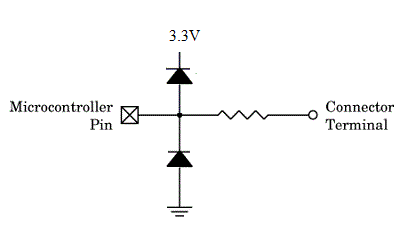
As a rule, if you are breaking out IO of an expensive MCU you should have a circuit similar to the one shown below.

Note that this offers both short circuit protection (resistor) and over voltage protection (diodes) in both directions (i.e. 3.3V + 0.6 and 0 - 0.6V)

To calculate the value of the resistor apply ohms law and choose a R larger than 3.3/Imax to be safe.

Edit: Possibly unclear what exactly you are trying to protect here. Regardless, you need to protect the I/O lines on your connector also.

Image source here enter image description here

\$\endgroup\$
5
  • \$\begingroup\$ Maybe the question is wrongly formulated but he wants to "protect the external supply lines". I found it strange too, but he's not talking about protecting the data lines. \$\endgroup\$
    – dim
    Commented Jan 23, 2017 at 20:09
  • \$\begingroup\$ Ok quite confusing indeed. Although he says he wants to protect the MCU. The MCU is probably not supplying power to the "supply lines", rather a seperate regulator is most likely. Comment added to ask for clarification. \$\endgroup\$
    – MAM
    Commented Jan 23, 2017 at 20:14
  • \$\begingroup\$ I suspect he's supplying his MCU directly with his 3.3V input (no regulator). But protection against short circuit wouldn't make sense, as I explained in my comment above. This is confused, yes. \$\endgroup\$
    – dim
    Commented Jan 23, 2017 at 20:18
  • \$\begingroup\$ Sorry i did't know that the data lines are also crucial. The devices is battery driven. There is a lot more going on than i thought. Maybe it is easier to ask the following question: Whats the common way manufactures of electronic devices with external connectors protect their devices from bad usage? \$\endgroup\$
    – perotom
    Commented Jan 23, 2017 at 21:22
  • \$\begingroup\$ If you have any MCU I/O going off to exposed connectors you should protect each pin by having the above circuitry on the PCB \$\endgroup\$
    – MAM
    Commented Jan 23, 2017 at 21:57
0
\$\begingroup\$

A low voltage drop solid state series current limiter can be constructed. It's a constant current pushing circuit that tries to push(* the maximum allowed load current. It's the same as in power supplies that have a linear regulator.

Check, if your system already has a current limiter in 3.3V output.

*) no active pushing, only no limiting until the load tries to sink too much current

Maybe you should to think to add a robust extra power supply for external stuff. This would be my solution. Note: you have to protect your data lines, too!

\$\endgroup\$
1
  • \$\begingroup\$ Thanks for your reply! I might have asked the wrong question. please see my added question. \$\endgroup\$
    – perotom
    Commented Jan 23, 2017 at 21:24
0
\$\begingroup\$

Check if the external sensor can operate at a voltage lower than 3.3V (2.5V is typical). In that case, a simple series resistor to limit the short circuit might be enough.

You'd take into account the total max supply current of the sensors to size the current limiting resistor. During short circuit, all of 3.3V will be across this resistor, so its power rating should be adequate for a continuous short circuit.

It's odd that the microcontroller would output a supply voltage at any meaningful current. Make sure this pin is not a voltage reference or such, and not intended to supply current.

For the data lines, you should use surge protection diodes, so when the EMF is (inevitably) coupled into the cable, the transient voltage induced in the cable is clamped to ground and does not cause the transient to be dissipated in your microcontroller.

\$\endgroup\$

Your Answer

By clicking “Post Your Answer”, you agree to our terms of service and acknowledge you have read our privacy policy.

Not the answer you're looking for? Browse other questions tagged or ask your own question.