0
\$\begingroup\$

I am redesigning a company product, it is a product for automotive maintenance and diagnostics. Currently in the product there is a FET BUS switch to perform the interface between the microcontroller and the product connector, to this connector can be connected several other devices that communicate with the microcontroller present in the product. Often it is necessary to perform external assembly to the to use the product, the assembly depends on the needs of the custumer and needs to be done by him. There is no single protocol and the communication used is diverse, so the lines need to be bidirectional, the only need is that the logical voltage levels for communication are digital of 0 and 5V.

The question I need to deal with then is the following: for reasons of incorrect assembly or carelessness with connectors on the part of the customer, there may be overvoltage in the communication lines and this is burning the bus switch. The bus switch we are using today, the SN74CBT3244DW, is powered by 5V, but it is very common, for the reasons described above, that customers accidentally put 12V on the communication lines. So,I need to reduce the amount of products that return for maintenance because of this issue.

To solve this issue, I imagined some solutions:

1) The product would no longer present the Switch bus internally, the idea would be to use an adapter that would be connected to the product and would make the interface between the product and the customer's assembly. In this adapter, there would be a protection circuit and, if happens some problem to the adapter, there would be needed only an exchange of the adapter and the customer would not need to send the product for maintenance, so, the customer would not be unable to perform other services offered by the product.

2) For the adapter circuit, the idea was to use some type of protection or insulation. However, as the lines of communication need to be bidirectional, I am facing difficulties in finding circuits that offer protection, or isolation and that have relatively low cost.

Would anyone have any circuit suggestions?

\$\endgroup\$
2
  • \$\begingroup\$ Take a look at the open source power handling portion of the Arduino Uno \$\endgroup\$ Commented Feb 18, 2020 at 18:07
  • \$\begingroup\$ The CAN hardware interface was, like, invented to handle not only direct shorts to the battery system but also to still work even if one of the data lines goes down. Some of the IC implementations are downright near bulletproof. I've never worked closely with CAN, but I remember watching as a design engineer did truly brutal things. It still worked. I was kind of impressed. I doubt this impacts what you are doing. But I'm mentioning it just in the off-chance it is useful. \$\endgroup\$
    – jonk
    Commented Feb 18, 2020 at 19:48

1 Answer 1

1
\$\begingroup\$

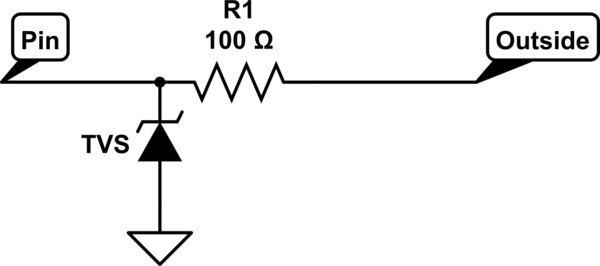
You could just use series resistors on the lines, depending on the communication protocols present. That's cheapest. Lots of components already have ESD diodes on their pins so series resistors will stretch those further.

You can also add external TVS diodes yourself but those can cost quite a bit. This lets you get away with a lower resistance since the external TVS can probably dissipate much more power than the pin's internal ESD diodes.

schematic

simulate this circuit – Schematic created using CircuitLab

\$\endgroup\$
9
  • 1
    \$\begingroup\$ @Daniel "it has action for a few milliseconds" Huh? You do realize that TVS diodes are extremely fast, right? Unless you mean the hazard time is too long, which is why the resistors are there with the TVS. You also never actually said why you think resistors aren't good in this situtation. It sounds more like you just have no idea what the communication protocols present can handle. As it stands you are looking for inexpensive, broad protection, that won't interfere at all with the signals. If such a thing existed, it would be in use everywhere. \$\endgroup\$
    – DKNguyen
    Commented Feb 19, 2020 at 3:52
  • 1
    \$\begingroup\$ @Daniel Resistors are in series with the pin.The TVS is between the pin and GND. Just like a zener diode regulator. \$\endgroup\$
    – DKNguyen
    Commented Feb 19, 2020 at 4:01
  • 1
    \$\begingroup\$ @Daniel If it fails, it should fail short, as most semiconductors do. \$\endgroup\$
    – DKNguyen
    Commented Feb 19, 2020 at 4:07
  • 1
    \$\begingroup\$ @Daniel Sounds like you need to review some basics about how voltage drops work. The resistor needs to be between the diode and the overvoltage to stop the diode from frying. The diode needs to be directly connected to the pin to clamp the voltage at the pin. That inherently means the resistor in series with the pin. Sure, a resistor in series can disturb the signals but its your job to find out how much resistance can be tolerated. \$\endgroup\$
    – DKNguyen
    Commented Feb 19, 2020 at 4:17
  • 1
    \$\begingroup\$ If you put the R in series with the D it will limit current through the diode, but it will not allow the diode to clamp the voltage at the pin. What stops the pin from seeing the full overvoltage when the resistor is in series with the diode? It's a straight connection from the overvoltage to the pin. \$\endgroup\$
    – DKNguyen
    Commented Feb 19, 2020 at 4:19

Your Answer

By clicking “Post Your Answer”, you agree to our terms of service and acknowledge you have read our privacy policy.

Not the answer you're looking for? Browse other questions tagged or ask your own question.