11
\$\begingroup\$

What does it mean to have a complex impedance?

For example, the impedance of a capacitor (in the Laplace domain?) is given by 1/sC (I believe) which equates to \$ \dfrac{1}{j \cdot 2 \pi \cdot f \cdot C}\$ where transients are neglected. What does it mean for the impedance to be imaginary?

I'm currently in my 2nd year of Electrical Engineering at University so, if possible, I'd appreciate a mathematically valid and thorough response if it's not too much trouble, with the reference of study material (web and paper resources) ideal.

Thanks in advance.

\$\endgroup\$
4
  • 7
    \$\begingroup\$ Aren't you studying exactly this in your courses? Surely you already have a textbook or two that goes into this in great detail. This is a very broad topic that is difficult to answer without a more specific question. \$\endgroup\$ Commented Mar 18, 2012 at 12:45
  • \$\begingroup\$ An additional resource \$\endgroup\$
    – clabacchio
    Commented Mar 18, 2012 at 12:59
  • \$\begingroup\$ The textbooks I have seem to assume this is already known from previous courses (and we weren't taught this). On top of this, my lecturers shuffled their order so we're probably going to be taught it later, but not before we need it. \$\endgroup\$
    – JonaGik
    Commented Mar 18, 2012 at 20:54
  • \$\begingroup\$ It seems that your couse left many topics untouched, and it's very inconvenient for an engineering course... \$\endgroup\$
    – clabacchio
    Commented Mar 18, 2012 at 21:23

7 Answers 7

11
\$\begingroup\$

TL;DR The imaginary part of the impedence tells you the reactive component of the impedance; this is responsible (among others) for the difference in phase between current and voltage and the reactive power used by the circuit.

The underlying principle is that any periodic signal can be treated as the sum of (sometimes) infinite sinewaves called harmonics, with equally spaced frequencies. Each of them can be treated separately, as a signal of its own.

For these signals you use a representation that is like: $$ v(t) = V_{0} \cos (2 \pi f t + \phi) = \Re \{ V_{0}e^{j 2 \pi f t + \phi} \} $$

And you can see that we already jumped in the domain of complex numbers, because you can use a complex exponential to represent rotation.

So impedance can be active (resistance) or reactive (reactance); while the first one by definition doesn't affect the phase of signals (\$ \phi \$) the reactance does, so using complex numbers is possible to evaluate the variation in the phase that is introduced by the reactance.

So you obtain: $$ V = I \cdot Z = I \cdot |Z| \cdot e^{j \theta} $$

where |Z| is the magnitude of the impedance, given by: $$|Z|=\sqrt{R^2+X^2}$$

and theta is the phase introduced by the impedance, and is given by: $$\theta = \arctan \left( \frac{X}{R} \right) $$

When applied to the previous function, it becomes: $$ v(t) = \Re \{ I_{0}|Z|e^{j 2 \pi f t + \phi + \theta } \} = I_{0} |Z| \cos (2 \pi f t + \phi + \theta ) $$

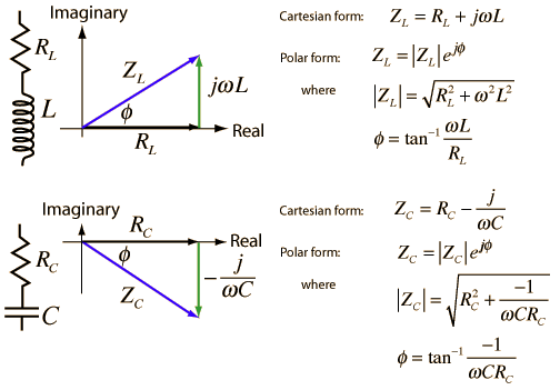
Let's consider the ideal capacitor: it's impedance will be \$ \frac{1}{j \omega C} = -\frac{j}{\omega C} \$ which is imaginary and negative; if you put it into the trigonometric circumference, you obtain a phase of -90°, which means that with a purely capacitive load the voltage will be 90° behind the current.

So why?

Let's say that you want to sum two impedances, 100 Ohm and 50+i50 Ohm (or, without complex numbers, \$ 70.7 \angle 45 ^\circ \$ ). Then with complex numbers you sum the real and imaginary part and obtain 150+i50 Ohm.

Without using complex numbers, the thing is quite more complicated, as you can either use cosines and sines (but it's the same of using complex numbers then) or get into a mess of magnitudes and phases. It's up to you :).

Theory

Some additional notions, trying to address your questions:

  • The harmonics representation of signals is usually addressed by Fourier series decomposition:

$$ v(t) = \sum_{- \infty}^{+ \infty} c_{n}e^{jnt} , \text{ where } c_{n} = \frac{1}{2 \pi } \int_{-\pi}^{\pi} v(t)e^{-jnt} \, dt $$

  • The complex exponential is related to the cosine also by the Euler's formula:

$$ cos(x) = \frac{e^{ix}+e^{-ix}}{2} $$

\$\endgroup\$
5
  • \$\begingroup\$ Thanks very much for your response. Regarding your v(t) equation, just to clarify, do you mean v(t) = v0 cos(2pi f0 t + phi) + v1 cos(2pi f1 t + phi) + ... + vn cos(2pi fn t + phi) (since the signal can be represented as a possibly infinite number of sinusoids of different frequencies)? Then, do you derive the R(V0 exp(j2pift + phi)) term from cos(x) = 0.5 exp(ix) + 0.5 exp(-ix)? If this is the case, where does the 0.5 exp(-2pift...) term go? Also, in your Ohm's law equation, presumably V(t) evaluates to a real expression but exp(j omega) doesn't, so how does this work? Thanks again. \$\endgroup\$
    – JonaGik
    Commented Mar 18, 2012 at 21:16
  • \$\begingroup\$ MMH many questions :). About the first, not exactly: check the Fourier series representation, but in theory also other decompositions are possible; about the exponential, yes, it's the Eulero equivalence. The same is true for the last question: the complex exponential gives the rotation, but then it's taken the real part only. \$\endgroup\$
    – clabacchio
    Commented Mar 18, 2012 at 21:22
  • \$\begingroup\$ Wow that's a quick response! Why is only the real part taken? That doesn't seem mathematically valid. Thanks again. \$\endgroup\$
    – JonaGik
    Commented Mar 18, 2012 at 21:27
  • \$\begingroup\$ Is this what I'm missing? "Aexp(i omega)... is understood to be a shorthand notation, encoding the amplitude and phase of an underlying sinusoid." from en.wikipedia.org/wiki/Phasor#Definition. Is the idea that the complex number representation is shorthand for the representation of an angle (phase) and a magnitude? \$\endgroup\$
    – JonaGik
    Commented Mar 18, 2012 at 21:35
  • \$\begingroup\$ @JonaGik yes, it's a convenient representation of sinusoidal signals, as also the wiki page says. I would say that every mathematical object is a shorthand to represent or solve some real problem... \$\endgroup\$
    – clabacchio
    Commented Mar 18, 2012 at 21:47
4
\$\begingroup\$

I am sure this will not answer entirely your question, in fact I hope this will complement the answers already given that seem to neglect: the concept behind the use of complex numbers (which, as already said, is just a fancy name for a type of mathematical "quantity", if you will).

The first main question here we should answer is why the complex numbers. And to answer this question we need to understand the need of the different sets of numbers, from the natural until the real numbers.

From the early ages the natural numbers allowed people to count, e.g, apples and oranges in a market. Then the integer numbers were introduced to address the "in debt" concept by means of negative numbers (this was a hard concept to understand at that time). Now, things get more interesting with the rational numbers and the need to represent "quantities" with fractions. The interesting about this numbers is that we need two integers, and not only one (as with the natural and integer numbers), for instance 3/8. This way of representing "quantities" is very useful, for instance to describe the number of slices (3) left in an 8 slices pie, when 5 were already eaten :) (you could not do this with an integer!).

Now, let us jump the irrational and the real numbers and go to the complex numbers. Electronics engineers faced the challenge of describing and operating a different type of "quantity", the sinusoidal voltage (and current) in a linear circuit (i.e, made of resistors, capacitors and inductors). Guess what, they found that complex numbers were the solution.

Engineers knew that sinusoids were represented by 3 components, that is, A (amplitude), \$\omega\$ (angular frequency), and phase (\$\phi\$): $$y(t) = A \cdot sin(\omega t + \phi)$$

They also realized that in a linear circuit the angular frequency (\$\omega\$) would not change from node to node, that is, no matter which point in the circuit you were probing, you would only see differences in terms of amplitude and phase, not frequency. They then concluded that the interesting (varying) part of a sinusoidal voltage (or current) was its amplitude and phase. So, just as we do with the rational numbers we need two numbers to represent the varying sinusoidal voltage in a linear circuit node, in this case (A, phi). In fact they realized that complex numbers algebra, that is, the way you operate and relate these numbers to each other fits like a glove with the way sinusoids are operated by linear circuits.

So when you say that the impedance of a capacitor is \$ \frac{1}{j \omega C} \$ i.e, (A=1/C, phi=-90º) in the above adopted notation, you are actually saying that the voltage is delayed 90º regarding the current phase. And please, forget that "transcendental" nomenclature about imaginary and complex... in fact we are talking about "quantities" with two orthogonal components (i.e, "that don't get mixed no matter how hard you shake them in a cocktail cup"), just like vectors, that represent two different physical aspects of the phenomena.

UPDATE

There are also some notes I highly recommend to read, "An Introduction to Complex Analysis for Engineers" by Michael D. Alder. This is a very friendly approach to the subject. In particular, I recommend the first chapter.

\$\endgroup\$
2
\$\begingroup\$

Using complex numbers is a mathematical way of representing both in phase and out of phase components - the current with respect to the voltage. Imaginary impedance doesn't mean that the impedance doesn't exist, it means that the current and voltage are out of phase with each other. Similarly a real impedance doesn't mean real in the everyday sense, just that the current is in phase with the voltage.

\$\endgroup\$
3
  • \$\begingroup\$ I understand these ideas conceptually, I was just wondering how a complex impedence actually works - what is the mathematical reason for it being complex and how is it derived? \$\endgroup\$
    – JonaGik
    Commented Mar 18, 2012 at 21:17
  • \$\begingroup\$ @JonaGik where was my answer lacking? I thought it was answering this mathematical reason... \$\endgroup\$
    – clabacchio
    Commented Mar 18, 2012 at 21:26
  • \$\begingroup\$ Is this right? Is the idea that the complex number representation is shorthand for the representation of an angle (phase) and a magnitude? So when we interpret a complex impedence we consider it to simply be representing the phase delay and the magnitude? \$\endgroup\$
    – JonaGik
    Commented Mar 18, 2012 at 21:37
2
\$\begingroup\$
  1. The descriptions below SEEK to demythologise what is meant by "complex" quantities in an R C L context. The concepts of 'imaginary" components are a useful metaphor which tends to blind people to the simple underlying realities. The text below talks in RC terms an does not touch on the mysteries of LC which are in fact no more mysterious in reality.

  2. It would be of greater benefit to you to do your utmost to address most of the points raised yourself using either a text book or internet search engine prior to seeking explanations from others BECAUSE this question is so very fundamental to the basics of AC circuits with reactive components. Dealing with difficult questions sets a precedence with how you will deal with similar things throughout your education and the internet has probably millions of pages dealing with this subject (Gargoyle says ~= 11 million but who can tell?). The degree of detail and thoroughness you ask for is unrealistic from a site like this given the vast truly amount amount of detail "out there". (Unless the site owners are trying to replicate a subset of Wikipedia).

SO - I wot that helping you get your head around the basics is a good idea so that you can pick it up and run with it from there. So ...

If you connect an input terminal to a series resistor to a capacitor and the other capacitor is "grounded" you get a series RC circuit:
Vin - resistor - capacitor - ground.

If you now apply a step voltage to the input the capacitor current will step to match but the capacitor will start to charge using this voltage to produce current in the resistor. The voltage increase will be exponential because the current flowing into the capacitor will beset by Icharge= V/R = (Vin-Vcap)/Rseries. ie as Vcap rises the potential across the resistor falls and so current decreases. In theory it will take an infinite time for Vcap to reach Vin but in practice it is more or less" there in about 3 time constants where
t = RC = the time taken for Iin to fall to 1/e th of its initial value. The what and why of the 1/e term you already know or will do after reading the references.

NOW, if we apply a square wave signal the capacitor will charge as above when input is positive and will discharge in a similar exponential manner when the input is grounded or negative. While the capacitor current will follow Vin and will be maximum when Vin transitions high/low or low high, the capacitor voltage, for the reasons described above will lag behind the input voltage. Once steady state has been achieved, if you plot Vcap and I cap you will find two waveforms offset by up to as almost 90 degree or as little as almost degrees where one whole input cycle = 360 degrees. How far the capacitor voltage is lagging behind its current depends on the input frequency and the RC time constant.

To the uninitiated this may look like magic (or the use of thiotimoline*), with a current waveform occuring up to 1/4 of a cycle before its voltage BUT this is just because the logical reason for this, as explained above, is not necessarily intuitively obvious on inspection.

If you start combing capacitors and resistors and inductors in various ways you need to be able to deal mathematically with the relative phases of the various waveform. [At first introduction it may seem that the phasors are set to stun].

Some competent figuring, or a sneak look at some of the 10 million or so web pages on the subject, will indicate that where you have two waveforms that vary in phase relation ship to each other and which are based on a mutual exponential relationship, then each waveform can be represented by a polar representation of the form [R,Theta] which in term can be represented as a complex number which has X and Y components which reflect the polar form.

The Polar "vector" which represents the voltage and current relationship in a given situation uses a rotating vector arm “metaphor” giving length of arm and phase angle relative to a reference. This “metaphor” can be replaced by an X and Y component where the magnitude of the polar form is given by R = sqrt(x^2 + y^2) and whose angle theta is given by tan^-1(X/Y) . This can be seen in diagrammatic form below.

enter image description here

From here

WARNING - don't be fooled by the terminology.

Note that the term "complex number" is simply Jargon. The use of sqrt(-1) is a useful part of the metaphor which allows the arithmetic to work BUT the actual quantities involved are entirely real and "ordinary". When reactive elements such as inductors and capacitors are used power will no longer be simply the product of the magnitude terms in the voltage and current vectors. ie The power from V.sin(fred) x I.sin(Josepine) does not (usually) = VI. This does not imply anything special or magical or complex or imaginary about the variables involved - it's just that they are time variant and their peak magnitudes will usually not coincide.


Extra reading - highly recommended:

Electrical impedance

RC circuit

LC circuit

Complex impedance calculator

  • I Asimov.
\$\endgroup\$
1
  • \$\begingroup\$ @Kortuk - The large majority of the above had been written prior to my initial written answer but I did not at that stage post it, but it may have been added in due course when better checked. As you will be aware, I often enough add large tranches of material to initial posts. In his case your carrot and stick approach (with no carrot) was rather demotivational, but it seems a shame to let misdirected motivational styles achieve their most normal effects. Some do respond well enough to gentle cuffings around the ear, but not most, I've found. Some here disagree :-). \$\endgroup\$
    – Russell McMahon
    Commented Mar 19, 2012 at 11:37
1
\$\begingroup\$

Expressing capacitance and inductance as imaginary resistances has the advantage that you can use well known methods of solving linear problems with resistors to solve linear problems with resistors, capacitors and inductors.

Such linear problems and their well known methods are for example

  1. Problem: calculating the resistance of two resistors in series
    Method: R = R1 + R2
    can also be used for calculating the impedance of resistor/capacitor/inductor in series with another resistor/capacitor/inductor
  2. Problem: calculating the resistance of two resistors in parallel
    Method: R = R1*R1/(R1+R2)
    can also be used for calculating the impedance of resistor/capacitor/inductor in parallel with another resistor/capacitor/inductor

  3. Problem: solving a network containing resistors, DC voltage and DC current sources
    Method: solving a simultaneous system of linear equations
    can also be used for solving a network containing resistors, capacitors, inductors, AC or DC voltage and AC or DC current sources

  4. etc.

All those formulas/methods that work with real resistance values (only resitors) and DC sources work just as good with complex values (resistors, inductors, capacitors) and AC sources.

\$\endgroup\$
0
\$\begingroup\$

Although there isn't necessarily any intuitive reason why using complex numbers to represent a combination of in-phase and out-of-phase signals should be useful, it turns out that the arithmetical rules for complex numbers fit very nicely with the actual behavior and interaction of resistors, capacitors, and inductors.

A complex number is the sum of two parts: the real part and an "imaginary" part, which can be represented by a real number multiplied by i, which is defined to be the square root of -1. A complex number may be written in the form A+Bi, with both A and B being real numbers. One may then use the rules of polynomial arithmetic to act upon complex numbers by treating i as a variable, but one may also replace by -1 (so e.g. the product of Pi×Qi is -P×Q).

At any particular frequency, one can determine how a network of resistors, inductors, and capacitors will behave by computing the effective impedance of each item and then using Ohm's law to compute the effective resistance of series and parallel combinations, and the voltages and currents through them. Further, because resistors, capacitors, and inductors are all linear devices, one can compute how the network will behave when combinations of frequencies are injected by computing what they will do with each particular frequency and then adding together the results. Complex arithmetic can be very useful when trying to analyze the behavior of things like filters, since it allows one to compute the output of the filter as a function of the input. Fed an input signal of some real number v volts at some frequency f, one can compute the voltage or current at any particular node; the real portion will be in phase with the injected waveform, and the imaginary portion will be 90 degrees out of phase. Instead of having to use fancy differential equations to solve the circuit behavior, one can relatively basic arithmetic with complex numbers.

\$\endgroup\$
-2
\$\begingroup\$

Complex numbers are used in electrical engineering for quantities that have a magnitude and a phase. Electrical impedance is the ratio of current to voltage. For AC currents and voltages, the current and voltage waveforms might not be in phase; the phase of the impedance tells you this phase difference.

\$\endgroup\$
1
  • \$\begingroup\$ Why the down-vote? \$\endgroup\$
    – nibot
    Commented Mar 25, 2012 at 10:23

Your Answer

By clicking “Post Your Answer”, you agree to our terms of service and acknowledge you have read our privacy policy.

Not the answer you're looking for? Browse other questions tagged or ask your own question.