1
\$\begingroup\$

I was wondering how can I find internal resistance of multimeter, in both voltmeter and ammeter capabilities?

I thought it was termed as input impedance but when I looked up the specs of multimeter, in example, Agilent 34410A Digital Multimeter, it said load impedance was 1 MΩ ± 2%, in parallel with <150 pF in True RMS AC Voltage, which did not make any sense to me at all.

I experimentally measured internal resistances for both voltmeter and ammeter capabilities of multimeter but I wanted to compare this experimental value to true value of internal resistances and make percent errors. Help please

\$\endgroup\$
1
  • \$\begingroup\$ Are you having trouble understanding the specification, or you just want to confirm it with a measurement? It will be a lot easier if you have two meters and some lab equipment such as CC/CV power supplies. \$\endgroup\$
    – user57037
    Commented Feb 5, 2017 at 7:40

3 Answers 3

2
\$\begingroup\$

In volt measuring mode, you can set up a voltage divider with two known resistor values and a known voltage source. You can then very simply compute the expected voltage you'd measure across one of the resistors. First, make sure your voltmeter is zeroed out without anything connected. Second, just apply the voltmeter to the voltage source itself and take down that reading as \$V_{source}\$. (Or tweak the voltage source's voltage so that you get a desired reading value.) Now apply your voltmeter across the chosen resistor and get a reading as \$V_{meas}\$.

Assume \$R_1\$ is the resistor across which you are not measuring the voltage. Assume \$R_2\$ is the resistor across which you are measuring. Then the effective resistance of your voltmeter will then be:

$$R_{V}=\frac{R_1 R_2}{\left(\frac{V_{source}}{V_{meas}}-1\right) R_2 - R_1}$$

This will probably work better when the values of \$R_1\$ and \$R_2\$ are equal to each other and within a factor of 5, higher or lower, of your voltmeter's expected impedance.

A similar method can be developed, assuming you have a current source and some resistors similarly near the expected impedance of your ammeter mode. The difference is that you'd set up your two resistors to be in parallel, rather than series and you'd take your current measurement using the ammeter in series with \$R_2\$ rather than across it, of course. Then:

$$R_{I}=\left(\frac{I_{source}}{I_{meas}}-1\right) R_1 - R_2$$

You should be able to work out the above equations, though.

A voltmeter should have relatively high impedance and an ammeter should have rather low impedance. So do not expect similar values.


But your meter is a \$6\:\frac{1}{2}\$ digit multimeter! It's possible you won't have similarly accurate equipment by which to judge it. But you should be able to roughly check it. Start with the voltmeter mode and use a pair of \$2.2\:\textrm{M}\Omega\$ resistor values to start. Use a voltage supply value that will test out each of the voltage ranges it accepts. (There are 5 ranges, see the manual.)

\$\endgroup\$
1
\$\begingroup\$

@jonk's answer was pretty good but had trouble seeing how exactly he derived the equation $$R_{v}=\frac{R_{1}R_{2}}{\left(\frac{V_{s}}{V_{m}}-1\right)R_{1}-R_{2}}$$

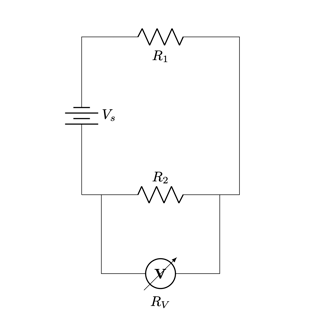
Say we have the following circuit:

Circuit of two resistors a power source and a voltmeter

$$ \begin{aligned} V_{m} &= \text{Voltage measured by the voltmeter across } R_2 \\ R_V &= \text{The resistance of the voltmeter} \\ R_c &= \frac{R_VR_2}{R_V+R_2} = \text{Equivalent resistance of } R_2 \text{ and } R_V \text{ in parallel} \end{aligned} $$ Using Ohm's Law calculate the value of R_c $$ V_{m}=I R_{c}=\frac{V_{s}}{R_{\mathrm{total}}} R_{c}=\frac{R_{c}}{R_{1}+R_{c}} V_{s} $$

Solve for R_c

$$ \begin{aligned} V_{m} &= \frac{R_{c}}{R_{1}+R_{c}} V_{s} \\ \frac{V_{m}}{V_{s}} &= \frac{R_{c}}{R_{1}+R_{c}} \\ \frac{V_{m}}{V_{s}}(R_1+R_c) &= R_c \\ \frac{V_{m}}{V_{s}}(R_1+R_c) - R_c &= 0 \\ R_c(\frac{V_{m}}{V_{s}} - 1) &= - \frac{V_{m}}{V_{s}}R_1 \\ \\ R_c &= \frac{\frac{V_{m}}{V_{s}}R_1}{1-\frac{V_{m}}{V_{s}}} \\ \\ R_c &= \frac{\frac{V_{m}}{V_{s}}R_1}{1-\frac{V_{m}}{V_{s}}} \left(\frac{\frac{V_{s}}{V_{m}}}{\frac{V_{s}}{V_{m}}} \right) \\ \\ R_c &= \frac{R_1}{\frac{V_{s}}{V_{m}}-1} \end{aligned} $$

Now sub in the definition of R_c

$$ \begin{aligned} \frac{R_VR_2}{R_V+R_2} &= \frac{R_1}{\frac{V_{s}}{V_{m}}-1} \\ R_VR_2 &= \frac{R_1}{\frac{V_{s}}{V_{m}}-1}(R_V+R_2) \\ R_V\left(R_2 - \frac{R_1}{\frac{V_s}{V_m} - 1}\right) &= \frac{R_1R_2}{\frac{V_s}{V_m} - 1} \\ \\ R_V\left(\frac{R_2 (\frac{V_s}{V_m} - 1) - R_1}{\frac{V_s}{V_m} - 1}\right) &= \frac{R_1R_2}{\frac{V_s}{V_m} - 1} \\ R_V &= \frac{R_1R_2}{\frac{V_s}{V_m} - 1} \cdot \frac{\frac{V_s}{V_m} - 1}{R_2 (\frac{V_s}{V_m} - 1) - R_1} \\ \\ R_{v}&=\frac{R_{1}R_{2}}{\left(\frac{V_{s}}{V_{m}}-1\right)R_{1}-R_{2}} \end{aligned} $$

\$\endgroup\$
0
\$\begingroup\$

Strange! My 34410A has almost exactly 10 Mohm input inpedance. As late as Friday, I had to take that into account for a high precision yet high impedance measurement.

In voltage mode, you can measure the current going in to your 34410A with an external multimeter and add that current times the (known) measure/divider impedance of your circuit and add that to your measurement.

In current mode, you can use an external multimeter and measure the voltage drop across the 34410A. It's a bit more tricky to say if you really need to take this into account or not since the current IS the current.

\$\endgroup\$
2
  • \$\begingroup\$ I wonder if your 34410 can measure its own amp scale resistance with a banana plug jumper between V and A + inputs with COM shared \$\endgroup\$
    – D.A.S.
    Commented Feb 5, 2017 at 9:06
  • \$\begingroup\$ May be possible. Datasheet should be good too :-) \$\endgroup\$
    – winny
    Commented Feb 5, 2017 at 10:31

Your Answer

By clicking “Post Your Answer”, you agree to our terms of service and acknowledge you have read our privacy policy.

Not the answer you're looking for? Browse other questions tagged or ask your own question.