1
\$\begingroup\$

I ask for help with a experimental assembly I am developing in the university, which is a small size power generation plant.

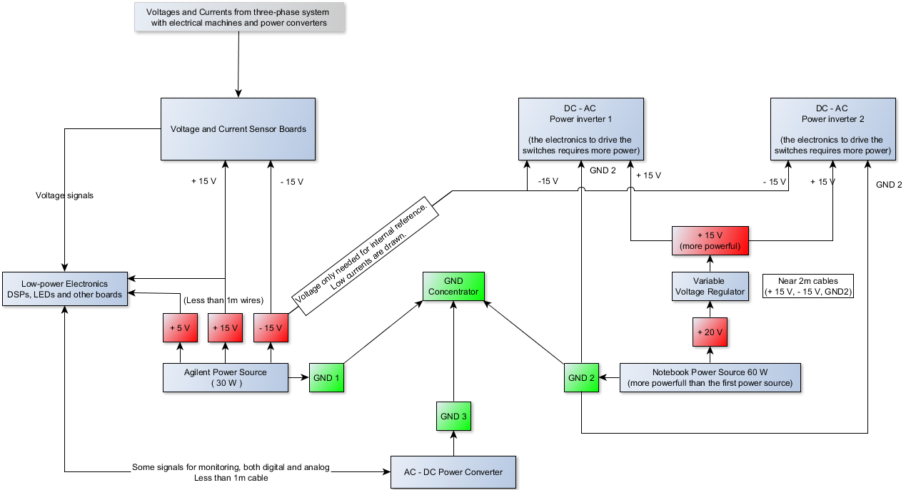
The system consists of a DC machine, a induction machine, several current and voltage sensors distributed in 4 boards, a AC-DC power converter to drive the DC machine, two power inverters configured as back-to-back and, of course, three DSPs, to control the whole system.

I sketched the diagram below trying to represent as close as possible the current physical assembly in the LAB. Turns out I am experiencing high levels of noise, voltage drops, reference divergences in several points, which is probably going to degrade the experiment.

LAB Assembly Diagram

My question is if you guys can help me with ideas to improve the system behavior regarding noise and references. Some considerations need to be made:

  1. I did not yet put the machines and the converters to work in full, they are only connected and the converters are powered on. Even like this, the system shows the aforementioned problems. I think when the machines and converters are working, it won't be pretty.
  2. All cables are NOT shielded, unfortunately. It is practically a standard of the devices that I own to use regular flat cables. I used, actually, CAT-6 twisted cables in some points, but not in the converters.
  3. As you can see in the sketch, the several boards and power sources need to be connect in the same referential, which may lead to ground loops. Should I connect them all to EARTH GROUND?

Thank you in advance for the help and the ideas.

\$\endgroup\$
2
  • \$\begingroup\$ Isolate and keep everything you can as far away from large magnetic fields. Magnetic fields are very difficult to shield. Separate ground currents and returns from shielding earths and if you can use opto-isolation between system blocks. All shielding earths should be connected to the same good earth spike. Lift your ground terminal off the scope and be careful - do not electrocute yourself. \$\endgroup\$
    – skvery
    Commented Mar 1, 2017 at 19:36
  • \$\begingroup\$ Your entire life, you've lived with noise and ground loops. That won't change. As for rejecting interfering signals, the literature on that subject is too vast for a useful answer here. \$\endgroup\$
    – Whit3rd
    Commented Mar 2, 2017 at 1:05

3 Answers 3

1
\$\begingroup\$

Grounding schemes can create problems, but not always. If you have problems with noise in your system here are two grounding configurations to check that are going to cause problems:

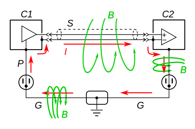
1) Ground loops: if you do have a shield you can make a giant loop from the shields and grounds of the devices. Sometimes its advantageous to break the shield at one end or the other to stop the currents. Another way is to use signal isolators to break the connection. It may also be possible to run the ground next to the cable and eliminate the loop that way too.

enter image description here

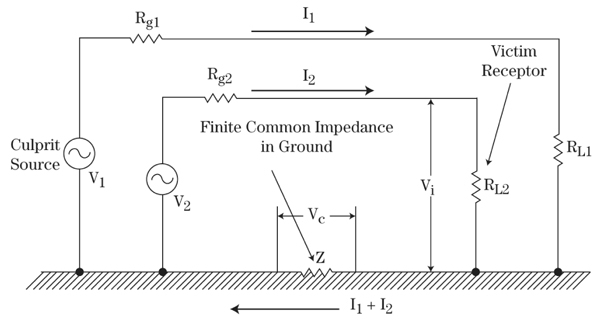
2) Common mode noise The other problem arises when you have a large current going through a fround that is shared by two devices. The large current will cause the resistance of the cable to create a voltage. (cables are usually under an ohm so for a 100mA current you'll get a 50mV offset from a 0.5Ω cable \$ V = I*R\$)

From https://interferencetechnology.com/designing-electronic-systems-for-emc-grounding-for-the-control-of-emi-3/

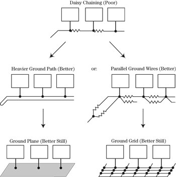
To combat this don't share grounds, sometimes star topologies are better. Using lower resistance cables helps also.
enter image description here

If you see AC interference on lines you can block the AC currents with a clamp on ferrite bead. EMC is more of an art than a science, the reason I say this is there are so many factors and each system is different.

\$\endgroup\$
2
  • \$\begingroup\$ Thank you for your answer. I think the actual configuration of my experiment is the Heavier Ground Path. Is it a good idea to connect it to EARTH GND? \$\endgroup\$ Commented Mar 2, 2017 at 10:44
  • \$\begingroup\$ Probably, since you want your system referenced to 0V, if you don't it will float. If you like the answer upvote, Thanks \$\endgroup\$
    – Voltage Spike
    Commented Mar 2, 2017 at 17:05
0
\$\begingroup\$

There are instrumentation signal transmitter-receiver pairs that are made for difficult environment in factorys, vessels etc... Use them. There are galvanic isolators that can break the loops.

Do not use the DC power distribution GND as the signal way. At least use balanced signals for sensors and low power controls.

Cables: Twisted pair prevent magnetic field to penetrate between balanced signal wires. If all weak signal wires run in a thick no-loop iron tube, then magnetic fields cannot cause confusing voltages to them. This means: One device gets all its nonisolated wires along one tube.

Read the comment (by skvery). It's full of details. Learn something serious about industrial instrumentation. Have a local consult.

\$\endgroup\$
2
  • \$\begingroup\$ Thank you for your answer. Could you explain further the second paragraph? I did not understand very well the "balanced signals" and "the DC power distribution GND as the signal way". About the cables, the twisted pair should be one signal and one GND, or it could be two signals wires twisted? \$\endgroup\$ Commented Mar 2, 2017 at 10:47
  • \$\begingroup\$ @FilipeTaveiros Balanced signal nees 2 signal wires +GND. The signal is between the signal wires. Twisted signal wires are needed against magnetic fields and crosstalk, too. Data transfer in LANs use balanced signals and audio in the recording studios, too. Web search will produce hundreds of hits. See an example: aviom.com/blog/balanced-vs-unbalanced The DC distribution GND is very poor as the return path of the signal because the current spikes directly cause disturbing voltages to signals. Balancing helps but is not enough if the noise spikes are too high, needs isolation, too \$\endgroup\$
    – user136077
    Commented Mar 2, 2017 at 22:25
0
\$\begingroup\$

CAT-6 twisted cables (STP) are an excellent choice but no good unless you also use an ethernet-like PHY to achieve very high CMRR or at least a CM choke on the receiver.

  1. I suggest twisted pairs for all power and signals in order to balance and reduce emissions and ingress into signal wires. Differential balanced signals are the best for immunity and the CM choke does this by raising the CM impedance of both wires while not affecting the Differential impedance Simple solution is add large Ferrite clamshell chokes of suitable mu to match frequency range of interest This adds a CM transformer to the wire bundle to raise CM impedance and thus reduce current and noise voltage

  2. You are learning the hard way that EMC issues exist in life and you must plan immunity more intelligently next time.

  3. If you studied the Laws of Ohm, Ampere, Lenz, Gauss and Ampere to realize you ought to be able to understand how to apply it with high impedance (low current) unbalanced loads and high magnetic line force fields and high electric fields radiating around the room.

  4. Just grab any scope probe and use your body as an antenna to see what E field you have then a large loop and short the probe to see the H field ( with a few turns may help) Even measure the voltage between a laptop case and earth ground using a two probes in differential mode or a DMM. You should may be surprised to see 25 to 75 volts avg.

Use a DMM to measure ground noise AC voltage and realize that it may be high impedance, which can be shunted to your Common instrument ground where analog signals are captured with an RF cap so AC current is not induced. (10nF)

  • best practice is to use STP or shielded twisted pairs with shield terminated only at source. and use line filters to reduce conducted noise and shielding or CM ferrite sleeves for high impedance cables.

e.g.

I get 25Vac between my laptop case (floating) and AC earth gnd and if I use my finger to make more capacitance on the laptop case with the probe. If use my body (fingers on each probe) to shunt that (safe )voltage I am effectively applying abut 1nF shunt capacitance and the DMM drops to < 1V and the external speaker hum goes away. Laptops are notirious noise receptors to floating SMPS noise. because the DC side is floating for ground fault current reasons. But when you know the AC ground signal has just high impedance or RF noise tying these grounds together will prevent AC leakage at line frequency but suppress SMPS buzz at higher freq.

ALways learn to use two 10:1 probes to measure noise and test it by connecting to the same point to get A-B flat line then you know your method is clean when you measure differential ground noise. ALso keep in mind the probe ground must be <1cm if you measure signals with a rise time <100ns since the probe ground L and cable C resonate near 20 Mhz.

This is just off the cuff advice from a Test Eng with 40yr experience.

Get and Read the entire book about EMC by Henry Ott. This will answer all your questions. ( you can find on web)

\$\endgroup\$

Your Answer

By clicking “Post Your Answer”, you agree to our terms of service and acknowledge you have read our privacy policy.

Not the answer you're looking for? Browse other questions tagged or ask your own question.