1
\$\begingroup\$

I have just started to learn using schematics in Eagle. I have a circuit in LTspice and since Eagle has an import facility for LTspice, I could open my LTspice circuit in Eagle schematic. So far so good, but unfortunately Im unable to move the components which are imported from LTspice schematics in Eagle. I can only move wires or groups. It is really annoying.

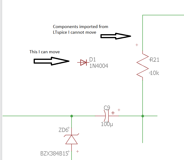
Below is an example, I can move 1N4004 because it is not a LTspice imported component but the rest I cant move which are imported from LTspice:

enter image description here

Does anybody experience the same issue? Or is there a solution to this?

edit: I think I needed to left click on plus sign. But is there a way to move only the component in Eagle? In LTspice there is two options drag and move where you can only move the component without the wires.

Is that possible to do in Eagle schematic as well?

\$\endgroup\$
10
  • \$\begingroup\$ I think I need to click on the plus sign but this time it moves together with the wire \$\endgroup\$
    – floppy380
    Commented Mar 13, 2017 at 17:46
  • \$\begingroup\$ Yes, the components are CONNECTED to the wire, so when you move a component, the wire follows. \$\endgroup\$ Commented Mar 13, 2017 at 17:48
  • \$\begingroup\$ see my edit, so it is not possible to move only the component without the wires? \$\endgroup\$
    – floppy380
    Commented Mar 13, 2017 at 17:50
  • \$\begingroup\$ The only reason why you would want to do this is if you wanted to delete the connection -- so you just delete the wire. \$\endgroup\$ Commented Mar 13, 2017 at 17:56
  • \$\begingroup\$ No i might also need to modify the circuit like in LTspice. \$\endgroup\$
    – floppy380
    Commented Mar 13, 2017 at 17:58

1 Answer 1

3
\$\begingroup\$

I don't see a little + sign in the middle of the resistor, for example. That means that the resistor wasn't added to the schematic properly as a device. It was apparently just drawn in the symbols layer.

If so, this is bad, as Eagle doesn't understand the connections between parts, and even that there are parts in the first place. All you have is a bunch of graphics in the schematic that happen to look like parts.

Basically, the script or whatever you are using to import this data is flawed.

Revised answer

On closer inspection, I do see the little plus signs for the components. They are quite a bit off from the centers of the parts, so I thought they were missing before. For example, the + origin marker for the resistor is above and to its left, halfway to the end of the arrow. The one for the diode is below and right of the part.

This means you probably do have a valid schematic that Eagle understands as such, but a rather annoying one. To move a part, run MOVE, then left-drag with the mouse on one of the little plus symbols.

\$\endgroup\$
5
  • 2
    \$\begingroup\$ @don-carlos more to say, these basic components are available in standard EAGLE libraries. Go get basic tutorial how to use EAGLE, otherwise you will just waste your time by misusing the tool (e.g. this one kb.gr8bit.ru/KB0015/…) \$\endgroup\$
    – Anonymous
    Commented Mar 13, 2017 at 17:54
  • \$\begingroup\$ @Anonymous which tool? Import tool? I can only simulate in LTspice, and dont wanna draw the same damn circuit two times. Thts time consuming. I didnt get whatcha mean? Should I redraw the circuit? \$\endgroup\$
    – floppy380
    Commented Mar 13, 2017 at 17:56
  • \$\begingroup\$ @don-carlos EAGLE tool. Can you tell what is the purpose you importing LTspice into EAGLE in first place? I guess you want to have functioning board at the end? If yes, then unfortunately this way you did the import will not yield good board. Please do not take personally, I am sorry if I offended you. The point is that to get good board design should conform specific EAGLE design rules. It may appear that you need to draw circuit - and then board - in EAGLE from the scratch. I would check with EAGLE support or with Element14 community. \$\endgroup\$
    – Anonymous
    Commented Mar 13, 2017 at 18:03
  • \$\begingroup\$ @Anonymous Imagine you designed a circuit in LTspice. And you want a PCB. Do you draw circuits from scratch in Eagle? What if you make a wrong connection? You might never notice it until you have the PCB and try a real test, since there is no simulation in Eagle. Im new so what do you suggest as a common practice? thanks \$\endgroup\$
    – floppy380
    Commented Mar 14, 2017 at 0:11
  • \$\begingroup\$ @don-carlos I do not have enough knowledge of LTspice; I use EAGLE; thus I would not be correct talking about common practices. Found this element14.com/community/thread/25645/l/… (on element14 site), the post says that you will anyway have to "correct" imported circuit diagram. My opinion is that if you create diagram from scratch you will prevent probably hidden issues introduced by the import, experience says that sometimes it is better to make things yourself than try correcting other's (import bot's) work \$\endgroup\$
    – Anonymous
    Commented Mar 14, 2017 at 7:14

Your Answer

By clicking “Post Your Answer”, you agree to our terms of service and acknowledge you have read our privacy policy.

Not the answer you're looking for? Browse other questions tagged or ask your own question.