10
\$\begingroup\$

I am currently designing a capacitive discharge spot welder and am running into the issue of switching.

I plan to use a few super capacitors in series to discharge around 1000A in a very short period of time (most likely less than 100 milliseconds). I plan on charging the capacitors to around 10V.

So I essentially need a device capable of delivering a short pulse of very high current. I do not want to dump the entire charge of the capacitor in one go, so SCRs are not a solution to my issue. I have been looking at MOSFETs, and this one catches my eye: http://www.mouser.com/ds/2/205/DS100728A(IXTN660N04T4)-1022876.pdf

However, I am unsure of how exactly to interpret the datasheet. Is the MOSFET capable of driving 1800A as its pulsed drain current states? Or is it limited to 660A (or even 220A), forcing me to wire a few of these in parallel? Or will one of these MOSFETS be fine? According to my preliminary calculations, a lone MOSFET connected directly to the capacitors without any other resistance would be dissipating around 900W, which seems to be within the range of the data sheet.

So essentially, am I interpreting the data sheet correctly, or do I need to order a few of these MOSFETs (and if so, how many would you guess?)

\$\endgroup\$
10
  • \$\begingroup\$ Assuming your pulse repeat time is long enough, that device should be able to handle it. Not sure about the super-caps and wiring though. The 900W thing does not mean much if your pulse repeat time is low. \$\endgroup\$
    – Trevor_G
    Commented Mar 14, 2017 at 7:21
  • \$\begingroup\$ It would be very helpful if you could describe your drain current more fully. Like with a graph. Are you thinking it is 1000A for 0.1 sec? Or would you be modulating the FET on and off during the 0.1 sec? What is the maximum pulse energy, in Joules? \$\endgroup\$
    – user57037
    Commented Mar 14, 2017 at 7:27
  • 2
    \$\begingroup\$ I have a feeling you are underestimating the current required to spot weld though. Minimum values I am seeing are like 6kA and up to 100kA. \$\endgroup\$
    – Trevor_G
    Commented Mar 14, 2017 at 7:57
  • 4
    \$\begingroup\$ If the total ESR in the caps and FET is 9 mOhms, at 1000A, that's a problem. You're dumping all the power in the welder and none in the spot being welded. You need most of the resistance where you want the heat to be. \$\endgroup\$
    – user16324
    Commented Mar 14, 2017 at 9:51
  • 1
    \$\begingroup\$ @DaPasta: discharging "2F" car audio caps with an SCR @ 15V works well for spot-welding to 18650s like you're (likely) doing. Using a CC/CV benchtop supply @ 10A will recharge them in under 10 seconds. Welding power is controlled by voltage into the caps. \$\endgroup\$
    – Bryan B
    Commented Mar 14, 2017 at 20:09

4 Answers 4

16
\$\begingroup\$

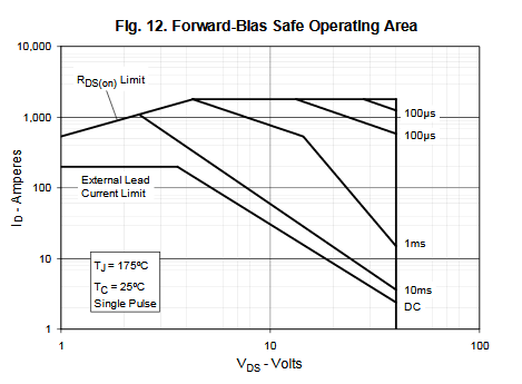
Look at page 4, fig.12, graph of safe operating area. That is exactly what you need.

enter image description here

You are talking about single pulse, right? You didn't mention any repetition or timing at all. If you open mosfet hard, say Rdson is 0.85mOhms. In case of 1000A the Vds will be less than 1V, so you have to look at the left side of graph.
There is no line for 100ms pulse, so you have to interpolate between DC and 10ms pulse. The safe current is much lower than 1000A. It is like 400A. And it is the maximum.

\$\endgroup\$
4
  • \$\begingroup\$ Thank you for the informative answer. Just to follow up, why do you assume that Vds is less than 1V? What stipulates its value? \$\endgroup\$ Commented Mar 14, 2017 at 8:28
  • \$\begingroup\$ Ohm's law. Rdson=0.85mOhm, I=1000A. V=R*I=0.85V. You have power source of 10V, but it does not mean that there will be 10V accross D-S, because there will be some other parts in your circuit with it's voltage drop, right? \$\endgroup\$ Commented Mar 14, 2017 at 8:39
  • \$\begingroup\$ Is "external lead current limit" some property of the test or that they just don't want you constantly shoving > 200 A through whatever wires you have bolted to the thing? \$\endgroup\$
    – Nick T
    Commented Mar 14, 2017 at 18:15
  • \$\begingroup\$ IMHO "external lead current limit" is the limit of physical bonds from case to silicon and limit of case itself. \$\endgroup\$ Commented Mar 14, 2017 at 18:26
3
\$\begingroup\$

I can confirm that this transistor does not do the job: http://www.eevblog.com/forum/projects/guesses-on-what-i-am-attempting-here/msg1236519/#msg1236519

This part is limited by bond wire current handling capacity - 200A.

\$\endgroup\$
2
\$\begingroup\$

it depends of on/off ratio, how much heat is produced. These transistors blocks have one limitation, that is a heat transfer. They are not so good when cooling down, another drawback is the large gate capacitance, so you will need a very expensive and powerful gate driver, even more if you will put them in parallel.

IMO you can do a better circuit if you use a bunch of D2Pak transistors in parallel. D2Pak can handle more current, but then you would need some complicated PCB.

\$\endgroup\$
3
  • \$\begingroup\$ Can you add some example of such transistors? \$\endgroup\$ Commented Mar 14, 2017 at 8:48
  • \$\begingroup\$ @Chupacabras Here it is, they are not D2Pak, but look the concept (pay attention on copper bus bar inside PCB): infineon.com/dgdl/… \$\endgroup\$ Commented Mar 14, 2017 at 9:59
  • \$\begingroup\$ I like the idea ;) \$\endgroup\$ Commented Mar 14, 2017 at 11:23
2
\$\begingroup\$

You should worry a bit more about the super capacitors. Some Murata "high current" models are rated for up to 10A. Other super capacitors have rating in the milliampere range.

\$\endgroup\$
1
  • 1
    \$\begingroup\$ I would love the sight of a briefcase sized bank of parallel supercapacitors capable of delivering 1000 A. \$\endgroup\$
    – paki eng
    Commented Jun 2, 2021 at 16:11

Not the answer you're looking for? Browse other questions tagged or ask your own question.