0
\$\begingroup\$

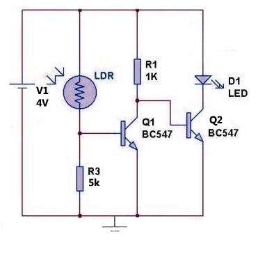
Here is my dark sensor circuit (below). However, my output current is very low. I get a maximum of 150mA to drive my strip LED. But I require atleast 450mA of output current.

I have tried many combinations. Tried emitter follower / tried replacing it with a N channel mosfet with not much improvements.

What can I do to achieve the desired 450mA?

I dont want to use a 3V relay in order to do this. Neither a solid state relay or a reed relay. Nor an optocoupler (low current). Any other alternate ways to do this?

Working circuit

\$\endgroup\$
9
  • \$\begingroup\$ Are you sure that your LED strip is going to draw 450mA from a 4V supply? MOSFET provide pretty low Rdson, but it did not work in your case. Can you provide the MOSFET's reference as well as the schematic (or is it the same as this one)? \$\endgroup\$
    – HatimB
    Commented Apr 19, 2017 at 9:42
  • 3
    \$\begingroup\$ What's the total forward drop across your LED Strip? You might not be supplying enough voltage. \$\endgroup\$
    – Tim M
    Commented Apr 19, 2017 at 10:51
  • 1
    \$\begingroup\$ The BC547 is a 100mA transistor. If you manage to push half an amp through it, it'll blow up. \$\endgroup\$ Commented Apr 19, 2017 at 11:45
  • \$\begingroup\$ Replace Q2 with a MOSFET, but you must use a logic-level FET. Regular FETs will not reliably turn on at your current levels with less than about 10 volts on the gate (as you have already discovered). \$\endgroup\$ Commented Apr 19, 2017 at 12:40
  • \$\begingroup\$ It draws over 1A when connected directly to a 4V batt without any resistor. Mosfet configuaration is same as this one. I have used 30N06 for my case. @HatimB \$\endgroup\$
    – soul6002
    Commented Apr 19, 2017 at 14:26

2 Answers 2

1
\$\begingroup\$

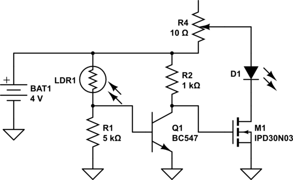
Here's a "corrected" version of your original circuit, using a 30A-rated MOSFET with Vgs(th)=2.0V and a max Rds(on) of 31m(ohm) @ 4.5Vgs when passing 18A of current (according to the charts, average Rds(on) for ~4Vgs should be under 30m(ohm) when passing only 450mA)

Notice that R4 is a varistor...obviously this wouldn't be necessary in a finished design, but when experimenting with LED drivers, I find it best to use a variable series-resistor until I get everything working right. Then, it's a simple matter to measure the resistance of the "working" setting on the varistor & replace with a near-value fixed resistor in "production models."
schematic

simulate this circuit – Schematic created using CircuitLab

-- -- -- EDIT -- -- --

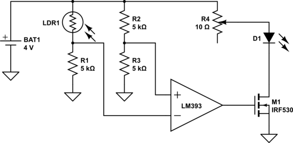
Here's an idea for a circuit I personally would use preferentially to the one above; though its a somewhat different topography than you're using:
schematic

simulate this circuit

In this circuit, when the resistance of LDR1 falls below the resistance of R2 (choose an R2 value for whatever "trigger point" resistance of LDR1 you want to switch at), the LM393 comparator's output will quickly transition from high-to-low; then when the resistance of LDR1 increases above that of R2, the comparator output will quickly transition from low-to-high.

The key advantages here are:

  1. The comparator transitions quickly, eliminating the "gray area" where the LEDs would be partially energized, but ineffective & simply wasting energy (as well as the MOSFET being in a linear region & heating up with higher dissipated energy itself)

  2. The comparator adds some hysteresis into the circuit, reducing the transitioning (flashing, or gray-area) that can often occur when light levels are very near the trigger point of a similar circuit that doesn't have enough hysteresis.
\$\endgroup\$
3
  • \$\begingroup\$ a better mosfet model just like hatimB suggested. i will try this out and let you know the result \$\endgroup\$
    – soul6002
    Commented Apr 22, 2017 at 16:26
  • \$\begingroup\$ Also, check your voltage levels with a multimeter while the circuit is in use with different light levels. You may find that different values for R1 &/or R2 will give more desirable performance properties. Personally, I'd omit Q1 & replace it with a comparator (LM393 would work well here) to drive M1...more "discrete" transitions & less power wasted heating up your MOSFET at "partially on" points turing on/off/on transitions. \$\endgroup\$ Commented Apr 23, 2017 at 1:02
  • \$\begingroup\$ @soul6002 See the additions to my answer under the "-- -- -- EDIT -- -- --" banner. \$\endgroup\$ Commented Apr 23, 2017 at 1:15
0
\$\begingroup\$

The BJT you're currently using should not be used for currents higher than 100mA.

The MOSFET you used has a threshold (Vgs-th) of 2 - 4V which does guarantee a drain current > 250µA. You need at least 4.5V to get a low enough Rdson -> high enough current for your application.

Use a MOSFET which has a lower Vgs-th given your conditions, then add a resistor in series with your LED strip to reach the desired 450mA. I do not suggest using the MOSFET in a specific operating point without feedback because its Rdson changes a lot with temperature and is not linear. You could however use a sensing resistor which you could use to control the LED current, but there is no need in my opinion to make this more complex if a series resistor meets your needs.

\$\endgroup\$
1
  • \$\begingroup\$ a good suggestion regarding the choice of mosfet. i will look for lower threshold models \$\endgroup\$
    – soul6002
    Commented Apr 22, 2017 at 16:22

Your Answer

By clicking “Post Your Answer”, you agree to our terms of service and acknowledge you have read our privacy policy.

Not the answer you're looking for? Browse other questions tagged or ask your own question.