0
\$\begingroup\$

I've been trying to solve the ac small signal analysis of this BJT amplifier for a while.

The question asks for the following:

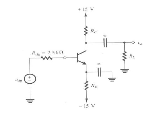
Q.4: For the BJT circuit (Figure 4), the signal source generates ac signal with zero DC. The transistor has \$\beta\$ =100, and ro =20 k ohms.

(a) Find RE to establish a DC current of IE= 0.5 mA. Assume VBE=0.7 V for conduction.

(b) Find RC to obtain VC = 5 V.

(c) Determine the system voltage gain with RL = 10 k ohms.

I was able to solve part a and b. I obtained RE = 28.85 kohms and RC = 20.2 kohms. But, I can't seem to solve part c. I used the t-model to try to solve for the gain. I considered Re to be just internal resistance of the amplifier. That is, re= \$ \frac{V_t}{I_e} \$ and I disregarded the previously found value for RE in part a (because of the bypass capacitor in parallel to Re). I eventually got to the answer \$ A_v \$= -99.2 v/v but the answer given by my teacher was \$ A_v \$=-66.26 v/v.

I've been trying for a couple of hours ( :( ) but I can't seem to be able to solve it. Any ideas?

enter image description here

\$\endgroup\$
6
  • \$\begingroup\$ I can immediately see that your calculation for the emitter degeneration resistor is wrong. There's another resistor you've forgotten to take into account. \$\endgroup\$
    – Hearth
    Commented Apr 26, 2017 at 4:03
  • \$\begingroup\$ Hey, are you sure that the emitter degeneration resistor is wrong? According to the answer given by my teacher, its \$ R_E \$ = 28.575 k ohms. As for the other resistor, I assume you're talking about the internal resistance between base and emitter looking into the emitter? i.e. \$ r_e \$? \$\endgroup\$
    – Ennis
    Commented Apr 26, 2017 at 4:09
  • \$\begingroup\$ Overall gain is Vo/Vsig, right? BJT gain you already calculated. But what is the voltage at the base of the BJT? It is not Vsig. In effect, the input impedance of the base makes a voltage divider with Rsig. Did you account for that? \$\endgroup\$
    – user57037
    Commented Apr 26, 2017 at 4:17
  • \$\begingroup\$ There is still Rpi. \$\endgroup\$
    – user57037
    Commented Apr 26, 2017 at 5:30
  • 1
    \$\begingroup\$ So re was 0.026/0.0005 = 52. So Rpi (resistance looking into base) is Re * Beta = 5200. So voltage at the base is Vsig * 5200 / (5200 + Rsig) = 0.675 Vsig. So the final SYSTEM gain is 0.675 * -99.2 = 67, which seems pretty close to what your teacher got. \$\endgroup\$
    – user57037
    Commented Apr 26, 2017 at 5:41

2 Answers 2

1
\$\begingroup\$

The only thing you seem to be forgetting is that the BJT gain is not the system gain. System gain is Vout / Vsig. But the BJT gain must be applied to the base voltage, not to Vsig.

You yourself computed the BJT gain as around 99 V/V. I am not double-checking that. Hopefully it is correct. But the base voltage can be computed using the votlage divider rule. First, we need Rpi, the resistance looking into the base. That is given by re * beta. Beta is given as 100, and re can be computed using Vt/Ic = 52. So Rpi is 5200.

The way I was taught to solve these problems is to view them as a series of gains which are multiplied together. The gain of the voltage divider formed by Rsig and Rpi is Rpi / (Rsig + Rpi). That is 2500 / (2500 + 5200) = 0.67. The gain from base to collector is -99.2 (per your calculation).

So the system gain is Vout/Vsig = 0.67 * -99 = -67 V/V.

Hope that helps. Let me know if I am wrong about anything.

\$\endgroup\$
2
  • \$\begingroup\$ Hi mkeith,I think you're correct but I have a follow-up question. So, \$r_e\$ and \$r_{\pi}\$ are internal components of the system that are always present? What I get confused about is that my book will have a hybrid-\$ \pi \$ diagram that only includes \$r_{\pi} \$ and a t-model diagram that only includes \$r_{e} \$ so I've come to think of them as exclusive to that model and can't be used in the analysis of the other model.As in, rpi is only for the hybrid pi model and can't be used for the t-model.I'm guessing this is all incorrect.Can you confirm?Thank you for your help, much appreciated. \$\endgroup\$
    – Ennis
    Commented Apr 26, 2017 at 14:29
  • \$\begingroup\$ Use whichever one is easier for you. Conceptually, the way I look at it is that re is the "real" resistance. Yes, it is inherent in the transistor. But it presents itself to the base as Beta * re because of the current amplification of the transistor. Basically, in the hybrid pi model, we are transforming the resistance re to an equivalent base resistance Rpi for convenient analysis. This applies to external emitter reistance also. The resistance looking into the base is (external emitter resistance + re) * beta. Been many years since I studied this, though! \$\endgroup\$
    – user57037
    Commented Apr 26, 2017 at 15:16
1
\$\begingroup\$

The schematic follows here:
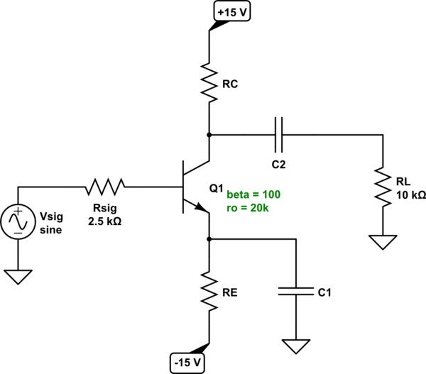
schematic

simulate this circuit – Schematic created using CircuitLab


For part (a) you know to consider the signal voltage as \$0\:\textrm{V}\$ (quiescent) for the purposes of computing the value of \$R_E\$. I assume you know how to perform the usual KVL loop from the signal source to the \$-15\:\textrm{V}\$ source, as:

$$V_{sig}+I_B\cdot R_{sig}+V_{BE}+I_E\cdot R_E + \left(-15\:\textrm{V}\right)=0\:\textrm{V}$$

From that, and knowing that \$I_E=\left(\beta+1\right)\cdot I_B\$, it's easy to find:

$$\begin{align*} R_E&=\frac{15\:\textrm{V}-V_{sig}-\frac{I_E}{\beta+1}\cdot R_{sig}-V_{BE}}{I_E}\\\\ &=\frac{15\:\textrm{V}-\frac{500\:\mu\textrm{A}}{101}\cdot 2.5\:\textrm{k}\Omega-700\:\textrm{mV}}{500\:\mu\textrm{A}}\\\\ &= 28.5752475\:\textrm{k}\Omega \end{align*}$$

So I believe your teacher is right about this detail. \$R_E\approx 28.575\:\textrm{k}\Omega\$.


For part (b), you know the collector current is \$I_C=I_E\cdot\frac{100}{101}\approx 495\:\mu\textrm{A}\$. You also know that this collector current must drop \$10\:\textrm{V}\$ across \$R_C\$, so \$R_C=\frac{10\:\textrm{V}}{495\:\mu\textrm{A}}=20.2\:\textrm{k}\Omega\$, as you already surmised.


For part (c), you are now dealing with the AC voltage gain. What first bothered me with your given situation is \$r_o=20\:\textrm{k}\Omega\$. That's a crazy low number. Let's take the DC quiescent point and follow this logic through. We know that \$r_o=\frac{V_A+V_{CE}}{I_C}\$, but this means that \$V_A=I_C\cdot r_o-V_{CE}=495\:\mu\textrm{A}\cdot 20\:\textrm{k}\Omega-5.7\:\textrm{V}=4.2\:\textrm{V}\$. (Which is pretty much insane. I don't buy it. But I suppose it must be accepted as given.)

I have to assume some value for \$V_T\$, so I'll assume \$V_T\approx 25\:\textrm{mV}\$ for the following. Knowing that \$g_m=\frac{I_C}{V_T}\$ and \$r_\pi=\frac{\beta}{g_m}\$ and \$r_e=\frac{1}{g_m}\$ then the total gain should be:

$$\begin{align*} \vert A_V\vert &=\frac{r_\pi}{r_\pi+R_{sig}}\cdot\frac{R_C}{r_e}\cdot\frac{r_o}{r_o+R_C}\cdot\frac{R_L}{R_L+\left(r_o\vert\vert R_C\right)}\\\\ &=\frac{\frac{\beta}{g_m}}{\frac{\beta}{g_m}+R_{sig}}\cdot\frac{20.2\:\textrm{k}\Omega}{\frac{1}{g_m}}\cdot\frac{20\:\textrm{k}\Omega}{20\:\textrm{k}\Omega+20.2\:\textrm{k}\Omega}\cdot\frac{10\:\textrm{k}\Omega}{10\:\textrm{k}\Omega+\left(20\:\textrm{k}\Omega\vert\vert 20.2\:\textrm{k}\Omega\right)}\\\\ &=\frac{100}{100\cdot \frac{V_T}{I_C}+2.5\:\textrm{k}\Omega}\cdot 20.2\:\textrm{k}\Omega\cdot\frac{20\:\textrm{k}\Omega}{20\:\textrm{k}\Omega+20.2\:\textrm{k}\Omega}\cdot\frac{10\:\textrm{k}\Omega}{10\:\textrm{k}\Omega+\left(20\:\textrm{k}\Omega\vert\vert 20.2\:\textrm{k}\Omega\right)}\\\\ &\approx 66.385 \end{align*}$$

Close.

I still can't stomach the \$r_o\$ value you have. But that's what works out in the end, if you accept it as valid.

\$\endgroup\$
2
  • \$\begingroup\$ So, I think I've found what my problem is. I didn't include \$r_{\pi}\$. So, to relate \$ v_{sig} \$ to \$v_i \$, I ended up using \$ v_{sig} = \frac{r_e}{r_e + r_{sig}} \$. In hindsight, I guess that was silly but I thought when using the T-model, \$r_{\pi}\$ should not be included. My understanding is that \$r_{\pi}\$ is used when you employ the hybrid \$ \pi \$ model and \$ r_e \$ is used when you use the T-model. I guess theoretically, my understanding of these concepts is still weak. Do you mind providing some insight into these concepts? Thank you again for the answer, it is a big help. \$\endgroup\$
    – Ennis
    Commented Apr 26, 2017 at 14:10
  • \$\begingroup\$ I want to point out something \$r_e = \frac{V_T}{I_E}= \frac{\alpha}{gm}\$ and the voltage gain is: $$|A_V| = \frac{R_C||r_o||R_L}{r_e}*\frac{\beta}{\beta+1} = \frac{20.2\:\textrm{k}\Omega||20\:\textrm{k}\Omega||10k \Omega}{50 \Omega}*\frac{100}{101} \approx 99.2556$$ and the input impedance effect: $$ \frac{r_\pi}{r_\pi+R_{sig}} = \frac{(\beta+1)r_e}{(\beta+1)r_e+R_{sig}}= \frac{5.05\:\textrm{k}\Omega}{7.55\:\textrm{k}\Omega} = 0.668874$$ so, the overall voltage gain is $$99.2556*0.668874 \approx 66.3895$$ \$\endgroup\$
    – G36
    Commented Apr 26, 2017 at 15:48

Your Answer

By clicking “Post Your Answer”, you agree to our terms of service and acknowledge you have read our privacy policy.

Not the answer you're looking for? Browse other questions tagged or ask your own question.