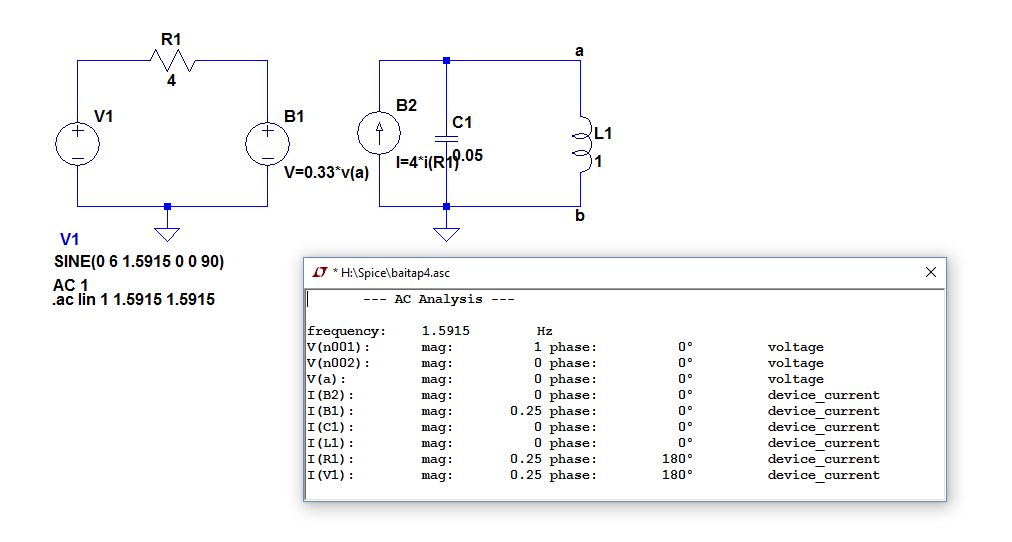
The result is not as I've expected. From my (manual) calculation, v(a) have to be 12V, but in this schematic it says zero. What wrong with it?
1 Answer
You can see something is not right because I(R1) is reported as non-zero, but I(B2) is 0.
From the LTSpice Help file on the expression syntax for the "B" element:
Expressions can contain the following:
o ...
o Circuit element currents; for example, I(S1), the current through switch S1 or Ib(Q1), the base current of Q1. However, it is assumed that the circuit element current is varying quasi-statically, that is, there is no instantaneous feedback between the current through the referenced device and the behavioral source output. Similarly, any ac component of such a device current is assumed to be zero in a small signal linear .AC analysis.
So it seems the "B" element (arbitrary controlled voltage or current source) is not much use (except possibly to set up the operating point) in an AC analysis. This makes some sense, because a nonlinear element would produce harmonic output that can't be accounted for in an AC analysis.
Since your relationship is linear, you can use the "F" element, a linear current-controlled current source, instead.
-
\$\begingroup\$ Thanks you, it's worked. By the way, is it possible to use current through other elements as a control current? From wiki, it said that you have to set a Current through voltage source to controlled F element.I set it as 'F1 0 a B1 4', it's worked. I tried to change it into
F1 0 a value={4*I(R1)}and then the result is as above. \$\endgroup\$ Commented Apr 30, 2017 at 0:47 -
\$\begingroup\$ Sorry, I don't know off the top of my head. I'd have to play around with a design and look at the netlist to work it out. \$\endgroup\$ Commented Apr 30, 2017 at 0:51
-
\$\begingroup\$ @ĐỨCNGUYỄNHUỲNH The moment you're using it with an equal,
=, it's internally transformed into a behavioural source. The same is true forGorEsources withvallue=.... This can be verified by viewing the extended netlist. If the relation is linear (as ThePhoton says at the end), you're much better off usingF(orH) sources than behavioural ones. \$\endgroup\$ Commented Apr 30, 2017 at 6:01 -
1\$\begingroup\$ Ah, I have just asked my professor, and she told me that I had to put a Zero Voltage at the point where I want to set as controlled current, so that I can use
I = 4*I(v_ref)and it worked. Thanks for your help. \$\endgroup\$ Commented May 3, 2017 at 3:13


AC 6instead. \$\endgroup\$