0
\$\begingroup\$

Assume that I want to determine the specifications of an analog front-end to build a digital FM demodulator to listen to radio broadcast stations, how would I start?

The broadcast frequencies of interest are im the range of let's say 80 to 110 MHz.How would I start to derive the needed sampling frequency and the number of ADC bits if I would go with an Direct Downconversion Concept?

(I think, additional specifications or assumptions have to be made such as target SNR and the topology of the used digital FM Demodulator but i don't know where to start)

\$\endgroup\$
2
  • 1
    \$\begingroup\$ You need to sample more than twice as fast as the bandwidth of the signal. The signal being the signal from one station so, go look up the modulation deviation to get your channel bandwidth. Presumably you will be under-sampling the carrier? \$\endgroup\$
    – Andy aka
    Commented May 5, 2017 at 15:59
  • 1
    \$\begingroup\$ Google is your friend to long answers ece.ucsb.edu/~long/ece145a/Introduction_to_Receivers.pdf intro to a SDR \$\endgroup\$
    – D.A.S.
    Commented May 5, 2017 at 16:07

1 Answer 1

3
\$\begingroup\$

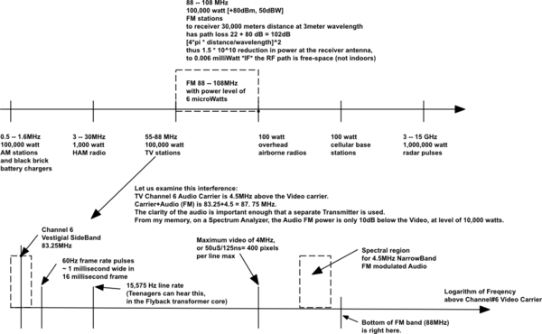
Having thought through the direct downconversion issues, the primary challenge is the dynamic range needed to accept massive energy alongside the weak FM signals.
schematic

simulate this circuit – Schematic created using CircuitLab

So you must provide some filtering at 88-108MHz, to establish the passband. We'll assume that passband is implemented with brickwall rolloff.

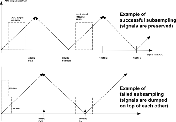
With a 20MHz bandwidth to digitize, while avoiding ADC spectral folding, you need to place the N*Fs/2 and (N+1)*Fs/2 on either side of 88-108MHz. An 80MHz Fs, Nyquist of 40MHz, will accept 88-108 with no aliasing of one FM station atop another. Thus the input 88-108 becomes 8-28MHz in ADC output codes. With no spectral folding or spectral overlapping.

Now for dynamic range, aka #bits. For quality music, you need 100dB SNR. That is 16+ bits. Will bandwidth compression, of the higher musical tones, provide 100dB SNR even if ADC only has 12 bits? Sounds like a FM_demod PHD topic. Surely this has already been written.

Here is the ADC spectral-folding behavior:
schematic

simulate this circuit

Your ADC sampling clock may be the difficult part of the signal chain. Low phase noise is needed. FM signals are easily trashed with wandering sampling edges, because with information in the Zero Crossing timing, an ADC with phasenoise in the sampling clock causes a worsened SNR.

Consider 100MHz RF input to the ADC. Clearly 10nanosecond sampling jitter has totally blurred out the signal, because we do not have any confidence as to where in the 10nS period the ADC actually grabbed a sample.

What about 10 picosecond sampling jitter? Let the RF input, at 100MHz, have 2 volts peakpeak swing. Slewrate is 1v * d(100MHz)/dt = 628Million volts/second. The uncertainly, using Tj = Vnoise/SlewRate, is Vnoise = Tj* SR = 10pS * 628e6 = 1e-11 * 628e6 = 628e-5 = 6.28e-3 = 6.28 milliVolts RMS uncertainty. Compared to 1vpp, or 0.707vrms, we only have 0.707/0.00628 = 110:1 SNR (7 bits), even if we were to use a 16bit ADC.

To reach 16 bits (limited by ADC internal flaws), we need at least 16-7 = 9 more bits of sampling-jitter improvement, or 6.02 * 9 = 54dB (500:1) cleaner sampling clock. We need 10pS/500 = 20 femtoSeconds total integrated jitter.

Spread over 80MHz clock rate (DC -- 80MHz), the density is 20fS/sqrt(80Mill) = 2 attoSeconds/rtHz jitter. Which is 2e-18 seconds. To achieve that, using 50 ohms as the total Rnoise and thus 4nanoVolts Vnoise, we need a SlewRate of 2 Billion volts/second in every circuit of the 80MHz clock generation circuit.

Notice the requirement: 2 Billion volts slewrate and Rnoise of 50 ohms max, in every circuit generating or touching or multiplexing or amplifying or dividing the 80MHz sampling clock.

\$\endgroup\$
5
  • \$\begingroup\$ Are the brick wall filters you mention for the whole 80 to 110 or for any one channel in that range. It's not a big deal but I didn't see it clearly. \$\endgroup\$
    – Andy aka
    Commented May 5, 2017 at 16:16
  • \$\begingroup\$ No it's not a university project, it's out of curiosity and for experimental purposes. \$\endgroup\$
    – Junius
    Commented May 5, 2017 at 16:22
  • \$\begingroup\$ Brickwall filters do not --- of course --- exist. Its the task of the system designer to determine how far down the out-of-band interferers (Channel 5 TV sound FM just below 88MHz; aeronautical radio just above 108MHz; radar pulses from 3Ghz to 9GHz) must be pushed down, and to implement those filters. My thinking was a passband, fairly flat but particularly with low delta-phase across any 150,000Hz FM energy allocation, of 88---108MHz. The ADC grabs that entire 20MHz, with whatever #bits you can afford, and the DSP does the rest. Is this the "direct downconversion" requested? \$\endgroup\$ Commented May 6, 2017 at 3:36
  • \$\begingroup\$ Do I understand this right that there is no mixer for downconversion necessary? The only thing is choosing fs so that it folds down the band of interest around DC? \$\endgroup\$
    – Junius
    Commented May 6, 2017 at 6:55
  • 1
    \$\begingroup\$ @Junius Yes, that is a standard technique and it is called undersampling. \$\endgroup\$
    – Kevin Reid
    Commented May 6, 2017 at 14:22

Not the answer you're looking for? Browse other questions tagged or ask your own question.