1
\$\begingroup\$

I am using Multisim to design the first stage of an analog signal processing block.

I am using the Op-Amp AD797AR from Analog Devices. I am trying to check if the opamp is inverting unity gain stable.

I have the following schematic enter image description here
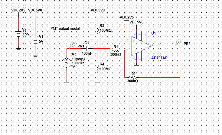
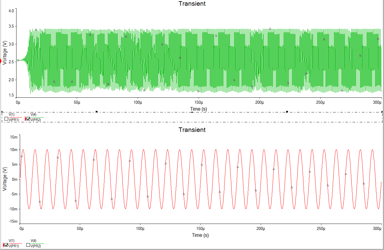
My input is a sine wave of 100 KHz peak of 10 mV but the output seems to be unstable.

enter image description here

How do I ensure stability for the AD797AR? What are some things I can check to ensure stability?

\$\endgroup\$
4
  • 2
    \$\begingroup\$ Your circuit is incorrect. That it not a "unity gain" configuration. Either feed your signal into the non-inverting input (for +unity gain) or use equal 'input' and 'feedback' resistors (for -unity gain). \$\endgroup\$
    – brhans
    Commented May 10, 2017 at 17:49
  • \$\begingroup\$ Sorry I meant inverting unity gain config. \$\endgroup\$
    – Ash
    Commented May 10, 2017 at 17:50
  • 2
    \$\begingroup\$ As I wrote - that is neither "unity gain" nor "inverting unity gain". So whatever you were aiming for - you haven't got it. Your circuit is wrong. Go back to your textbook and look at an inverting unity gain opamp circuit - you'll see 2 resistors usually labeled as Ri and Rf. where are they in your circuit? \$\endgroup\$
    – brhans
    Commented May 10, 2017 at 17:51
  • \$\begingroup\$ Thanks brhans. Sorry I didn't realize this mistake. i will try. Thanks \$\endgroup\$
    – Ash
    Commented May 10, 2017 at 17:55

3 Answers 3

5
\$\begingroup\$

The AD797 op amp is not really unity gain stable without adding a capacitor and it isn't really designed for a supply as low as 5 volts. Read the data sheet. I wouldn't use 100 M ohm resistors either. Look at table 7 in the data sheet and note the low ohmic values for the resistors used. The 300 kohm resistors are far too high.

\$\endgroup\$
2
  • \$\begingroup\$ Adding a capacitor where? \$\endgroup\$ Commented Nov 5, 2020 at 3:41
  • \$\begingroup\$ @PeterMortensen where would you normally find this information? \$\endgroup\$
    – Andy aka
    Commented Nov 5, 2020 at 9:18
3
\$\begingroup\$

Read the datasheet thoroughly.

The device is only marginally stable at Av=10 and. it is unstable at unity gain.

add a few ohms to V+ in and découplé Vcc as shown in fig 38 after you increase Av>= 10

THIS DEVICE IS NOT INTERNALLY COMPENSATED and has a huge GBW product.

\$\endgroup\$
2
\$\begingroup\$

You have the input signal wired to the wrong place. The output should directly drive the negative input of the opamp. The input signal should be applied to the positive input, not the negative.

Your circuit basically adds a capacitive load to the output of the opamp, then injects a signal on top of that. What you are seeing is not meaningful. Connect the input signal correctly, try again, and report back.

If you really want to check the opamp in inverting configuration, then you have to wire that right too. In that case, put a resistor between the output and inverting input, and a equal resistor between the input signal and the inverting input.

\$\endgroup\$
2
  • \$\begingroup\$ Hi Olin, thanks for your response. i am trying to simulate inverting unity gain config, I corrected the mistake in schematic. Still the output seems to be unstable. \$\endgroup\$
    – Ash
    Commented May 10, 2017 at 18:01
  • \$\begingroup\$ You must have Rfb/Rin ratio of 10:1 or higher for this opamp. You also must use +10 volts for the supply, and +5 volts on +Vin. \$\endgroup\$ Commented May 11, 2017 at 5:00

Your Answer

By clicking “Post Your Answer”, you agree to our terms of service and acknowledge you have read our privacy policy.

Not the answer you're looking for? Browse other questions tagged or ask your own question.