5
\$\begingroup\$

I am working on an audio circuit featuring the MOS Technology 6581 SID. The circuit works on a solderless breadboard with acceptable but still quite noticable noise. I am now going to design a PCB, but first I want to know what I could change in the circuit to further reduce noise. This is what I considered:

  • Using more (differnt sized) decoupling capacitors
  • Using a voltage regulator for VDD of the SID instead of taking it straight from the power supply
  • Using a separate voltage regulator for VCC of the SID
  • Using switching regulators instead of linear ones
  • Using a better power supply

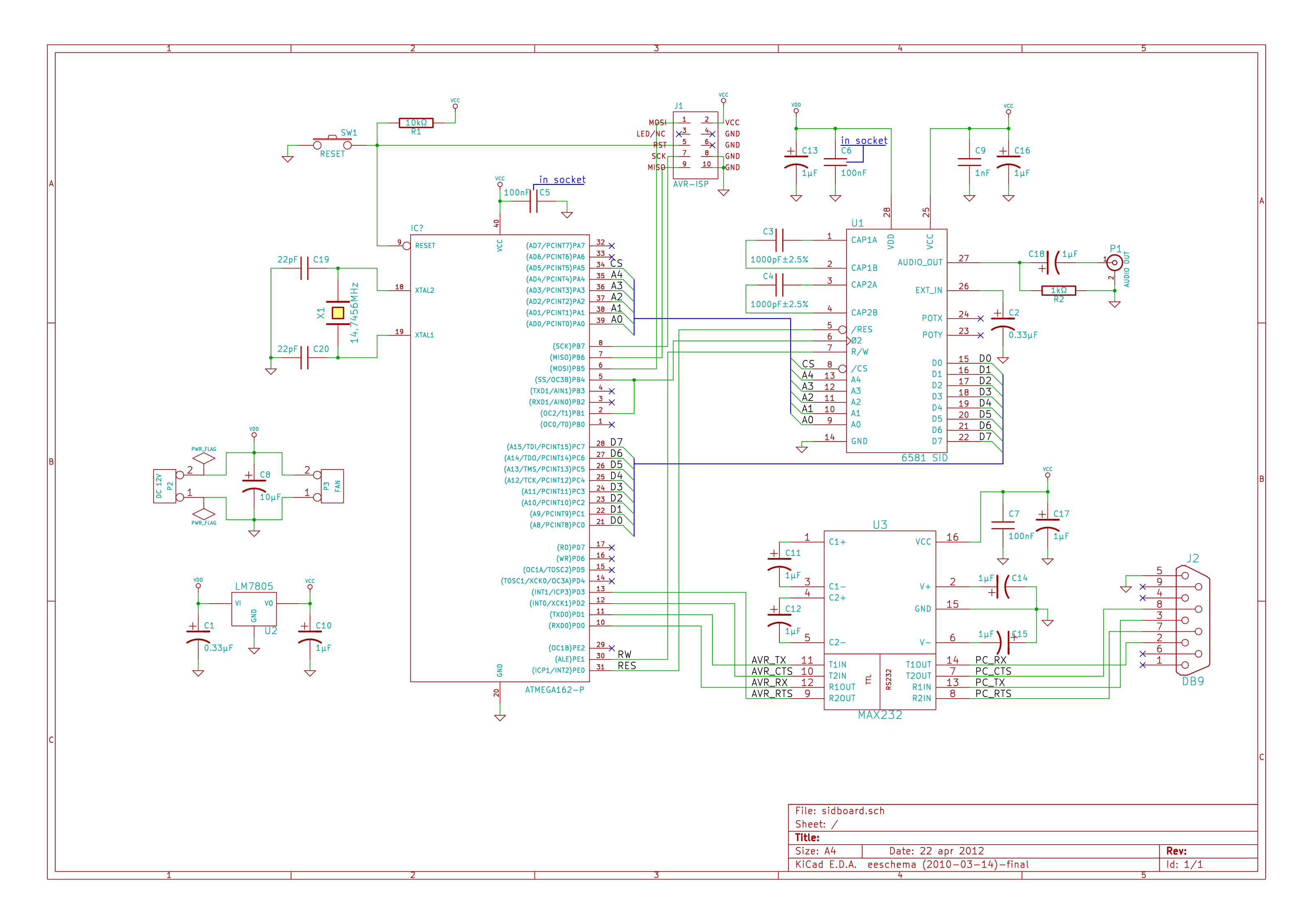
Schematics (click here for unscaled version) circuit
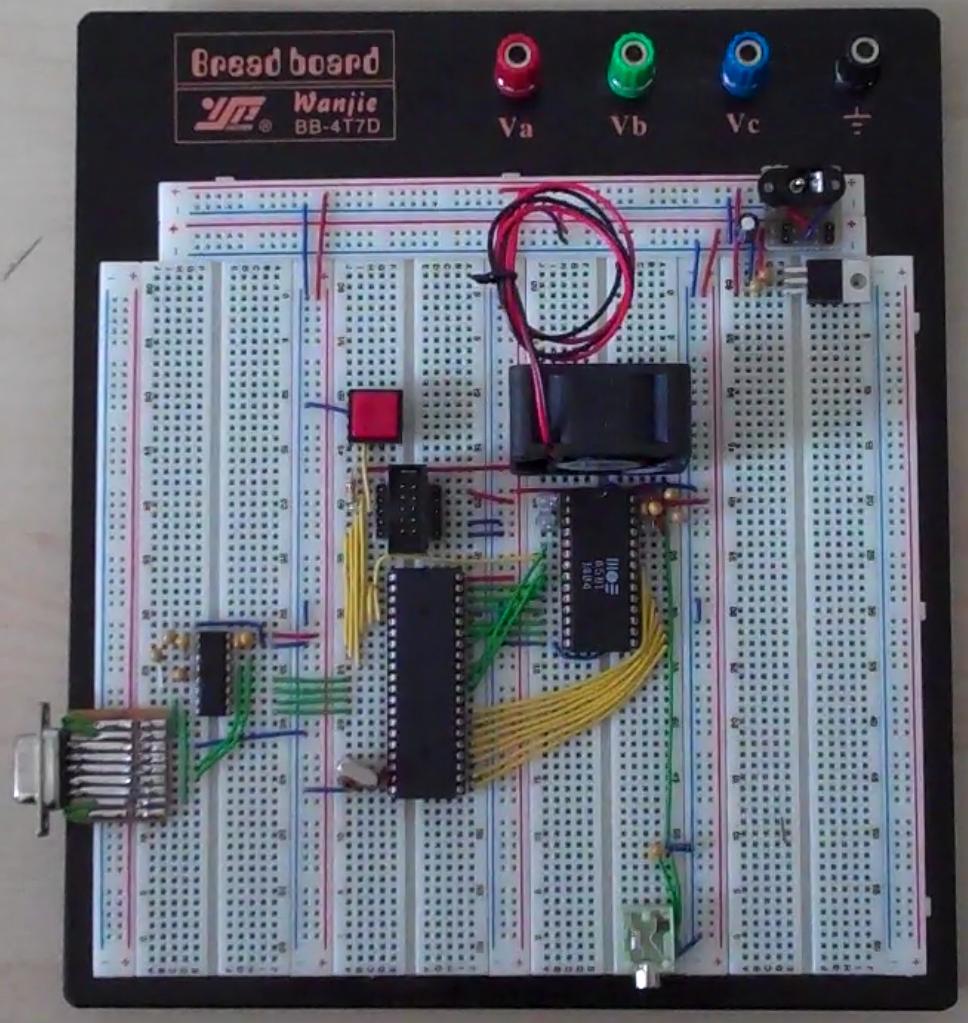
Breadboard setup breadboard

\$\endgroup\$
4
  • \$\begingroup\$ right click, view image works. but I'll add a link. \$\endgroup\$ Commented Apr 28, 2012 at 12:22
  • \$\begingroup\$ @stevenvh - Just right click, Open in new tab. \$\endgroup\$ Commented Apr 28, 2012 at 12:23
  • \$\begingroup\$ @noah1989 - Woah, is that a C64 part ? \$\endgroup\$ Commented Apr 28, 2012 at 12:23
  • \$\begingroup\$ @Rocketmagnet yes :) \$\endgroup\$ Commented Apr 28, 2012 at 12:24

2 Answers 2

6
\$\begingroup\$

The core problem that you're experiencing is probably that the SID is not a low-noise device. When I had a C64 way back in the day we would turn up the volume to listen to the noise-- as a debugging aid. We could tell, roughly, if the CPU crashed by the noise generated from the SID!

That being said, there are some things that you can do to minimize the noise. I have no idea if any of these will reduce the noise enough in your case, but it's a start. Here goes, in no particular order:

  1. Use some linear regulators to give the SID its own power rails. Use low-noise regulators. Use large ceramic caps (make sure the regulator can handle them) instead of electrolytic or tantalum. You might only be able to get these caps in SMT.
  2. Filter the output of the SID to remove high-frequency noise. A simple low pass filter set with the cutoff at around 16-18 KHz would work. The idea here is to reduce the audio that you can't hear so that it doesn't interfere with downstream devices. (Someone is going to say that they can hear up to 20 KHz, ignore them.)
  3. Use series termination on all signals between the CPU and the SID. Use the highest value that you can get away with (start with 50 ohm). This should reduce the edge rates and overshoot/undershoot on the bus, and reduce that getting into the audio.

There you go!

\$\endgroup\$
2
  • \$\begingroup\$ heh, I'm not the only one who listened to the noise of a computer as a debugging aid. :-) There were some enterprising people who used computation patterns to modulate the EMI and broadcast music, and yet others who worked on transmitting EMI in such a way as to transmit a different image than what they were displaying for Van Eck phreaking. \$\endgroup\$
    – akohlsmith
    Commented Apr 29, 2012 at 1:23
  • 1
    \$\begingroup\$ The noise even helped me when debugging the code that runs on the AtMega interfacing the SID. Normal noise: Clock running, Higher pitched noise: Clock stopped, program crashed: Lower pitched noise and humming: UART communication :D \$\endgroup\$ Commented Apr 29, 2012 at 22:51
4
\$\begingroup\$

I would certainly go for three separate linear regulators. One for the AT Mega and MAX232. One for the SID Vdd and one for the SID Vcc. In my humble experience with ADCs, using separate regulators for analog and digital has usually made a significant improvement in SNR.

As I'm sure you know, there are also some long green audio wires passing close to those yellow digital wires. Move and shield those if you can.

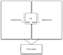
When you lay out the PCB, don't forget to use separate analog and digital ground planes.

Analog and digital ground planes.

\$\endgroup\$
1

Your Answer

By clicking “Post Your Answer”, you agree to our terms of service and acknowledge you have read our privacy policy.

Not the answer you're looking for? Browse other questions tagged or ask your own question.