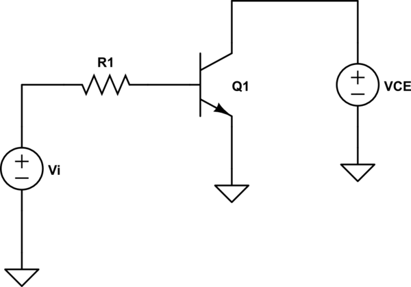
From a theoretical POV your prof is WRONG. You correctly calculated the total power dissipation of your BJT.
Your professor might be right only in an approximate way: if both the BJT quiescent point is in the active region AND its \$h_{FE}\$ is at least 10-20, then he is (approximately) right, because then \$I_B\$ would be much less than \$I_C\$ and \$V_{BE}\$ would be about 0.6V, so that the \$V_{BE} \cdot I_B\$ contribution would be negligible.
In this case you cannot be deemed to be wrong, but only to be overzealous.
Note, however, that if the BJT is saturated, i.e. both its junctions are forward biased, \$h_{FE}\$ no longer relates \$I_B\$ to \$I_C\$, i.e. \$I_B\$ cannot be assumed to be much lower than \$I_C\$. In this case the base-emitter junction dissipation can be as relevant as the collector-emitter junction dissipation, and your professor would be completely wrong.
This latter case is particularly important for power BJTs, since their \$h_{FE}\$ is quite small (~20, or less sometimes), so \$I_B\$ is not so much lower than \$I_C\$ even in the active region. Thus, to bring them into full saturation you sometimes have to provide an \$I_B\$ that is comparable to \$I_C\$. Considering that \$V_{CE(sat)}\$ could be less than \$V_{BE(sat)}\$, this means that in some particular (but not theoretical) case base dissipation could be slightly higher than collector dissipation. Neglecting it would be disastrous, then (especially when choosing the right size for the heat sink!).
BTW, If your professor doesn't think that the \$I_B\$ term is right, simply redraw the transistor circuit with the base powered by the Thévenin equivalent of the bias network (and whatever is connected to the base), so that it can be modeled by a simple two-terminal network. Then calculate the power that that equivalent circuit provides to the base of the BJT and ask where does that power go, if not into the BJT?
Conservation of energy is a basic law of nature. I hope your professor doesn't need a book reference to believe that!

