0
\$\begingroup\$

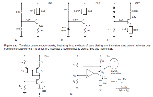
I need a variable current source as part of a power supply for an experiment I'm building. This part should heat up a filament, so the load is pretty constant. Timing is not a factor either. So what I'm looking for is a pretty simple solution, much simpler than a lot of circuits I find online. But all the simple circuits, like the ones attached are often calculated for small currents. I need a regulation between 1.5A and 2.5A and my question is if someone has experience with such simple circuits and higher currents. Of course I would use other parts like power transistor and other resistors but heat and efficiency could be problems, but I don't know to which degree. I study physics, so I'm no expert in electrical engineering.

I hope someone could give some intuitive answer. Thanks

Simple current sources

\$\endgroup\$
4
  • \$\begingroup\$ Is this meant to be a fixed 2A output, or do you need to be able to control it from 1.5 to 2.5 A? What maximum voltage must this supply be able to put out? What power voltage do you have available, or can you get whatever power supply is required? \$\endgroup\$ Commented Jun 6, 2017 at 13:13
  • \$\begingroup\$ I need to be able to control it in this range. I could get whatever power supply is needed i guess. Was thinking to take a normal 12V or 24V power supply which can deliver 5A or so. It needs to be as small as possible. \$\endgroup\$
    – Niklas
    Commented Jun 6, 2017 at 13:15
  • \$\begingroup\$ Sorry, english is not my first language. What more infos do you need? \$\endgroup\$
    – Niklas
    Commented Jun 6, 2017 at 13:17
  • \$\begingroup\$ I'd go with something like B or the op-amp one which is more adjustable. Transistor needs to be beefy and have a heatsink. Sensing resistor needs to be small and rated for the power. \$\endgroup\$
    – Trevor_G
    Commented Jun 6, 2017 at 13:20

1 Answer 1

3
\$\begingroup\$

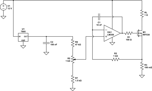
Something like this should work for you. With the values shown, R3 needs to be rated for about 1W and M1 needs a heat sink for up to 30W if RL can be shorted. The current sink has a compliance of the supply voltage minus about 0.5V so don't use excessive voltage for V1 (needs to be about 7V minimum for U1 to work properly) if you want to keep the heat sink reasonable. Or you can add a resistor in series with RL to move some of the power dissipation off the transistor.

"Or you can add a resistor in series with RL to move some of the power dissipation off the transistor." You mean from the Drain to GND, Right?

schematic

simulate this circuit – Schematic created using CircuitLab

\$\endgroup\$
2
  • \$\begingroup\$ Thank you very much. would you mind sharing what function the capacitors have? \$\endgroup\$
    – Niklas
    Commented Jun 6, 2017 at 13:56
  • \$\begingroup\$ C1 is part of a compensation network with R1/R2 to prevent M1's gate capacitance from loading the output of the op-amp and reducing its phase margin (possibly oscillating). C2 is a bypass capacitor to make people feel better (it's typically not necessary). You should also have a cap across V1, 1000uF/25V electrolytic for example. \$\endgroup\$ Commented Jun 6, 2017 at 13:58

Your Answer

By clicking “Post Your Answer”, you agree to our terms of service and acknowledge you have read our privacy policy.

Not the answer you're looking for? Browse other questions tagged or ask your own question.