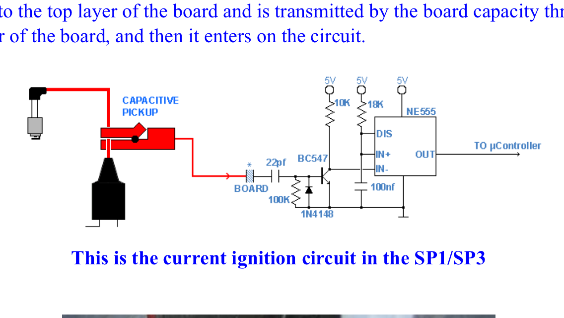
From the description, you have to form a capacitor using the PCB. One plate on the top layer and one plate on the bottom layer (same dimensions and position).
You connect one plate to your pickup clamp and the other to the 22 pF capacitor.
Now don't ask me for dimensions of the plates. I also imagine that the PCB thickness is important as well. Maybe even critical to have a minimum strength to prevent arc-over (in which case you also need enough clearance around that plate). If you would know the required capacitance you can calculate the area of the plates, but otherwise it's pretty much guessing. I'd probably start with finger-print sized plates for no obvious reason.
Your second part is guessed correctly. The 5 V goes to Vcc of the NE555. The schematic follows the custom to draw Vcc at the top and GND at the bottom.
Still having unlabeled pins I'd consider bad style (imagine an inverting circuit where voltages go below zero and GND is suddenly on the top and stuff).

