1
\$\begingroup\$

I am trying to build digital tachometer for my motorcycle Yamaha FZS600 Fazer 2002. I have a problem with reading signal from CPS sensor. It is hall effect sensor, I suppose. I found the plug of it. It has two wires. One is GND so the other must be the signal. I have no oscilloscope to probe it so I connected it to the soundcard oscilloscope through the voltage divider and op-amp as can be seen in below schematic.

schematic

simulate this circuit – Schematic created using CircuitLab

I adjusted the R1 and R2 values with a 10k potentiometer and got signal presented in picture 1. It looks nice (it looks like it would be no problem reading it with a uC).

Picutre 2 - CPS signal read by soundcard

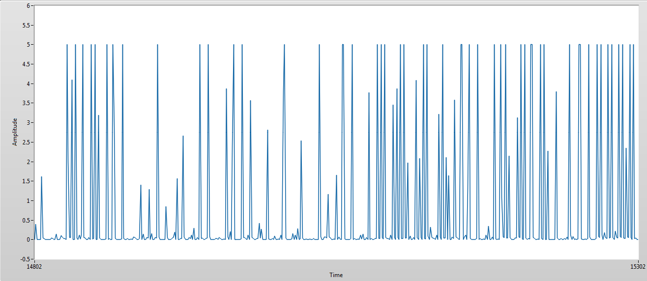
In the next step I connected the same circuit to a analog pin of an Arduino and uploaded simple program to constantly read voltage on that pin and transmit it through serial. The result can be seen in picture 2. That doesn't look like the waveform from picture 2 at all. First of all the signal read by a soundcard is inverted but it is reasonable. The signal read by an Arduino is meaningless. The question is what is the proper circuit to read a signal from such sensor.

Picture 2 - CPS signal read by Arduino AnalogRead()

The LM358 is single-supplied from 12 V with a 1uF capacitor to GND. Adjusted values are: R1 = 9.27 kOhm R2 = 1.79 kOhm

With no voltage divider or with smaller R1 it seems that my circuit disturbs motorcycle's ECU reading of CPS and the engine runs unevenly or stops.


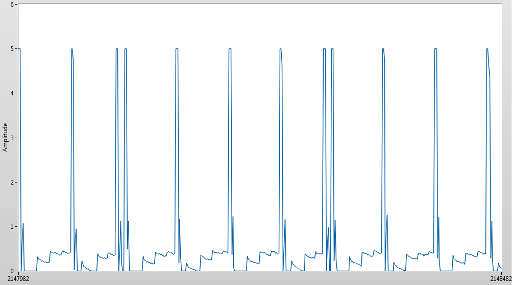
@Andy aka, you were right about aliasing problem. According to your advice I succesfully sampled the CPS signal with Arduino at a higher rate. The required modification was to change a prescaler of ADC clock. I've done this according to this tutorial http://www.microsmart.co.za/technical/2014/03/01/advanced-arduino-adc/ and here it is what I've got

CPS signal sampled with Arduino with a faster ADC clock

Nevertheless question about proper circuit for reading CPS signal and filtering out noise still remains. When I turn the knob of potentiometer voltage divider such that R2 becomes greater and R1 smaller the waveform is getting more noisy. Furthermore I am wondering what level voltage that CPS signal can have. Arduino indicates it's 5 V but how can I know it isn't greater?

\$\endgroup\$
6
  • 1
    \$\begingroup\$ It's a digital (on/off) signal. Why would you connect it to an analog input? \$\endgroup\$
    – Transistor
    Commented Jul 28, 2016 at 14:22
  • \$\begingroup\$ Arduino's come with their own easy to implement interrupt. I've used it numerous times for rotary encoders and it seems like it's just the thing you might need. arduino.cc/en/Reference/AttachInterrupt \$\endgroup\$
    – user103993
    Commented Jul 28, 2016 at 14:25
  • \$\begingroup\$ I was using interrupts but the readings was not what I expected that's why I connected it to an analog input, to see what is going on in the circuit. \$\endgroup\$ Commented Jul 28, 2016 at 14:29
  • \$\begingroup\$ Presumably the double pulse (in the waveform from the soundcard) indicates Cylinder #1. \$\endgroup\$
    – Steve G
    Commented Jul 28, 2016 at 14:30
  • \$\begingroup\$ @Steve G The double pulse is not a problem. Actually the soundcard waveform is nice and easy to interpret but why waveform on analog input of Arduino is so noisy? \$\endgroup\$ Commented Jul 28, 2016 at 14:35

1 Answer 1

1
\$\begingroup\$

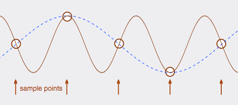
It's called aliasing - if you don't convert the analogue signal to digital at a fast enough rate you get near enough garbage. Consider this picture of a sinewave sampled at too low a rate: -

enter image description here
(source: emusic at www.iu.edu)

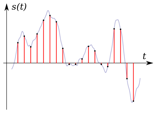
Imagine the brown waveform is your analogue signal. The arrows are when the Arduino samples the brown signal and the blue dotted line is what you might construe those samples to mean i.e. nothing like the original signal because you are sampling at too slow a rate. You need to "sample" at a rate that is greater than twice the highest frequency of interest such as here: -

enter image description here

However, you should be able to see that the above sampling will miss nuances in the waveform that change too quickly.

\$\endgroup\$
5
  • \$\begingroup\$ Ok, so I will try to sample with a higher rate. I'm still wondering why the op-amp itself, as a voltage follower, disrupts the CPS circuit though in theory it has high input impedance. Why it needs a voltage divider before? \$\endgroup\$ Commented Jul 28, 2016 at 20:50
  • \$\begingroup\$ How big is the CPS signal and what voltage (+ and -) is the LM358 powered from? \$\endgroup\$
    – Andy aka
    Commented Jul 28, 2016 at 21:39
  • \$\begingroup\$ I have problem to determine a voltage level of the CPS signal because I have no proper oscilloscope. The LM358 is powered from +12V and GND. Powering it from +5V results in limiting output to 3.5 V. Maybe I should try a rail-to-rail op-amp? \$\endgroup\$ Commented Jul 29, 2016 at 8:58
  • \$\begingroup\$ When powered from 12V what is the output signal in terms of maximum and minimum for the signal? \$\endgroup\$
    – Andy aka
    Commented Jul 29, 2016 at 12:22
  • \$\begingroup\$ Your 2nd graph (the one that I believe demonstrates aliasing) occupies 500 ms and there appears to be substantially less than 4500 samples in that window. There looks to be more like 450 samples in that window or maybe one every millisecond. Given that one pulse appears to occupy approximately 1 millisecond you have an aliasing problem. \$\endgroup\$
    – Andy aka
    Commented Aug 4, 2016 at 11:41

Your Answer

By clicking “Post Your Answer”, you agree to our terms of service and acknowledge you have read our privacy policy.

Not the answer you're looking for? Browse other questions tagged or ask your own question.