0
\$\begingroup\$

I am trying to connect a tacho that is fitted on a DC motor to an MCU / FPGA. It is being used to provide speed feedback of the DC motor.

At full speed the tacho generates around 5.5Vdc which is converted with an ADC before being connected to the MCU / FPGA. As this task requires the motor to go in both directions the tacho also generates negative voltages.

If the voltage was negative only it is easy to convert it with an inverting op amp setup.

Is there a circuit that can convert the 0 to -5.5Vdc to an equivalent positive voltage and leave the positive generated voltage unchanged?

\$\endgroup\$
5
  • 2
    \$\begingroup\$ If you don't need to detect low voltages from slow rotation, you might be able to use a full wave bridge rectifier. Another possibility would be a voltage divider and biasing to half the ADC input range. \$\endgroup\$ Commented Nov 11, 2020 at 15:48
  • 1
    \$\begingroup\$ Do you have both wires of the tachometer available, or does the assembly come to you with one grounded? \$\endgroup\$
    – TimWescott
    Commented Nov 11, 2020 at 16:04
  • 1
    \$\begingroup\$ Also, do you mind generating \$\pm\$10V supplies or similar on the board, or is there some VCC supply you want to stick with? \$\endgroup\$
    – TimWescott
    Commented Nov 11, 2020 at 16:06
  • \$\begingroup\$ @ChrisStratton I do require the detect the voltages from slow speed so rectification is not an option. I am worried about losing too much accuracy as I was considering 8 bit resolution but I can go bigger. I'll look into biasing \$\endgroup\$
    – David777
    Commented Nov 11, 2020 at 16:09
  • \$\begingroup\$ @TimWescott I have access to both wires of the motor and the tacho and neither are grounded. The motor is rated for up to 24Vdc so I don't mind generating any supplies less than 24V on the board or on external circuitry. \$\endgroup\$
    – David777
    Commented Nov 11, 2020 at 16:11

2 Answers 2

1
\$\begingroup\$

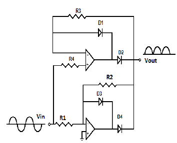
You should be able to use a precision full-wave rectifier like this: -

enter image description here

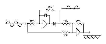
You will need a positive and a negative rail and another inverting stage to turn the output shown above into a positive signal. But, this is just one example of many precision full-wave rectifiers on the web and maybe a different one would suit your needs such as this: -

enter image description here

\$\endgroup\$
5
  • 1
    \$\begingroup\$ Thanks for the answer! I see how biasing a precision full wave rectifier could work. I will look into it and come back if I have any more questions. \$\endgroup\$
    – David777
    Commented Nov 11, 2020 at 16:31
  • 2
    \$\begingroup\$ If you are concerned about slow speeds then you may not want a rectifier solution as that will fail to distinguish direction, including the case where the motor is spinning at the right rate but being spun by the load in the opposite of the desired direction, leading to no corrective drive being applied. So if you need low speed accuracy you may want a biased bidirectional setup instead so that zero speed is half range on the ADC and you can do absolute comparisons against a goal rather than having to guess a direction "mode bit". \$\endgroup\$ Commented Nov 11, 2020 at 16:40
  • \$\begingroup\$ @David777 are you done with this Q and A yet? If not, is there anything that you need to know? \$\endgroup\$
    – Andy aka
    Commented Nov 17, 2020 at 12:12
  • \$\begingroup\$ @Andyaka Yes I am finished with this Q & A. The tacho is actually AC and not DC like explained in this post. I have posted a new question if you are interested in answering \$\endgroup\$
    – David777
    Commented Nov 17, 2020 at 12:34
  • \$\begingroup\$ @David777 I'll take a look but if this is done then you need to select an answer and formally accept it. The fact that you were mistaken in assuming the tacho was an AC output type for this question is irrelevant. \$\endgroup\$
    – Andy aka
    Commented Nov 17, 2020 at 12:36
1
\$\begingroup\$

Let me ask a different question - are you trying to figure out the direction with this voltage flip circuit ?

If yes, and if schematic / BOM changes are still possible you may want to consider using an optoelectronic encoded disk . You can easily figure out the direction and speed while using a simple SPI / I2C interface. Only limitation would be how fast do you need the refresh the RPM value ? I would save FPGA logic and go for a pure digital solution. This has several advantages, namely analog debugging is minimum, analog part degradation absent in the long run, circuit Isolation is great and you can get all sorts of sensors for rugged to super precise ones(64 bits).

\$\endgroup\$
1
  • \$\begingroup\$ @DisplaynameNo I am only interested in calculating the speed in RPM at present. I have actually posted a new question as my tacho is actually an AC generator and not DC like explained above. If you are interested in answering my new question I have posted, I am more than happy to hear it. \$\endgroup\$
    – David777
    Commented Nov 17, 2020 at 12:39

Your Answer

By clicking “Post Your Answer”, you agree to our terms of service and acknowledge you have read our privacy policy.

Not the answer you're looking for? Browse other questions tagged or ask your own question.