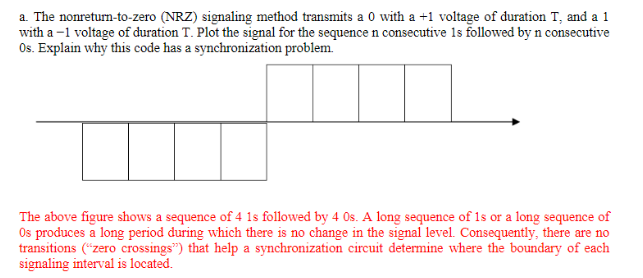
For reference, here is the plot of the signal:

The polarity is defined a + for 0 and - for 1. This plot therefore shows the bit sequence 11110000. Note that the polarity is one of the design choices. it could have been done either way, but this example clearly says that negative voltage represents 1 and positive voltage 0. There is nothing wrong with that.
The important thing to notice is that during a long sequence of the same bit, the signal is flat. The diagram above shows lines indicating the bit boundaries, but those aren't really in the signal.
Think about how a receiver has to decode this signal. When there is a transition, like in the middle of the example above, it knows it's at a start of a bit. However, the only way to know where subsequent bits are without further transitions is by timing. No matter how good the transmitter and receiver clocks, eventually they will get out of sync by more than ½ bit. When that happens, the receiver is actually sampling the line level for each bit in a neighboring bit.
Let's put some numbers to this. Let's say both the transmitter and receiver use crystals for timing that are good to 50 PPM. That's very easy to get. The total error between the two can therefore be up to 100 PPM. 100 PPM (parts per million, 10-6) is 1 part in 104 = 10,000.
½ bit time is the guaranteed to fail skew. Let's say you don't ever want to the skew to exceed half of that, or ¼ bit time. With 1 bit time error in 10,000 bits, that means you can send at most 2,500 bits without a re-sync and still say within spec. If you are willing to require both sides to use crystals, then you could in theory get away with that.
If you want your communication link to work when both sides are using RC oscillators good to about 2%, then the total mismatch can be 4%, or 1 part in 25. ¼ bit time error can then occur after only 6¼ successive bits of the same polarity. Since bits come in whole chunks in this protocol, that means you can't send more than 6 bits of the same polarity in succession. By the 7th bit, the receiver could already be sampling the wrong bit.
It seems this example was meant for you to come to the realization that strict NRZ coding doesn't work in the arbitrary case.
The next lesson might be about how to tweak NRZ to make it useful in practice. I'm not going to write a book here, so I'll give you two things to look up:
- UART protocol. This sends bits in chunks of (usually) 8. It allows for re-synchronization each chunk by having a start bit before the chunk, then a stop bit after the chunk. The stop bit guarantees the line state so that the start of the next start bit is a transition.
- Bit stuffing. That's a common term I'm sure you'll find lots out there about. Basically, you never send more than some maximum number of identical bits in a row. When you hit that number, you artifically add a opposite bit to the stream. That forces a transition, which allows the receiver to re-sync it's clock. The receiver knows the stuffing algorithm, so can remove the extra bits after reception.
There will be lots out there about these two examples of modified NRZ in actual use.


