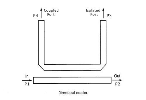
If I were you would include a stripline Directional Coupler to antenna port on PCB so you can detect Return loss and output power with a pin diode peak detector to DMM using sweep test pattern on your radio. Then you don't need an SA and you have a built-in test method. We call this Design for Testability (DFT) which is a MUST HAVE for any design, not an afterthought!!
You might use this on your prototype.

Normally directional coupler (splitters) are used for this. You can choose the coupling factor to minimize loss like -20 dB sample ports so insertion loss is low. So if you are ok with this, look for microstrip or stripline DC-20. These have 4 ports on PCB and you you have 2 U.FL ports for the DC-20 and 1 for the External Antenna. If you choose to use only 3 of 4 ports and antenna port as the output then the DC-20 is terminated with 50R on the unused port.
Advice.
You need a minimum number of accessories. U.FL to SMA to N cables
Do a tolerance analysis on your RF PCB design. dielectric k has a wide tolerance as well as track tolerance on impedance. Testing at board shop includes test coupons is about >100$ This allows them to control your designated track impedances with TDR testing and the tune G codes for give batch of laminate to obtain this result.
Learn "What is a Directional Coupler?" and how to measure Return Loss with it. such as for antenna. without spending $600 ( research)
Semi-rigid coax works best after calibration using SMA . learn to make.... later
If Analyzer has only 1 port then save gen response and then normalize when reading DUT response to get ratio.
Since s11 input impedance may be not 50 Ohms, the transfer function will then depend on source impedance so ratios must consider this using directional couplers... aka splitter
Bonus.
make/buy?
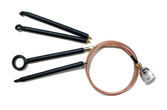
design these loop antenna for EMI nearfield noise detection.

ref info: http://www.semtech.com/images/datasheet/rf_design_guidelines_semtech.pdf
https://www.everythingrf.com/rf-calculators


