9
\$\begingroup\$

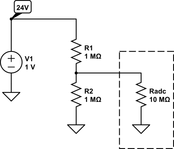
I am measuring the voltage of a 24 V battery using the ADC from Arduino Uno. I use a voltage divider to bring the voltage below 5V (the maximum the ADC can accept).

I noticed that as long as the ratio of R1 and R2 is the same for my voltage divider - it's better to use higher resistance values to avoid slowly discharging the battery. I tried using resistors up to mega-ohm range. What do I sacrifice by using higher and higher resistances? The intuition tells me, that this cannot go forever, because high enough resistor would be equivalent to an open circuit.

By reading other similar questions it seems I might be sacrificing accuracy, but I am not sure, as other questions typically have a different setup.

If it is accuracy, is there a formula for that? When does the standard voltage divider formula break down? Giga-ohms, Tera-ohms? How to calculate that?


P.S. I am aware of this question, however the answer there seems very convoluted, comparing load and no-load scenarios (where I don't have any load at all). If that is the answer, I do not understand it.

\$\endgroup\$
4
  • \$\begingroup\$ Generally you use a 10% rule of thumb - the current taken at the output of the divider should be less than 10% of the current through the divider. The lower this % the more the output voltage agrees with the 'theoretical' calculation. \$\endgroup\$ Commented Jun 27, 2017 at 16:53
  • 1
    \$\begingroup\$ 10k max because Atmel says so. That's it, simple as that. \$\endgroup\$
    – Cano64
    Commented Jun 27, 2017 at 19:31
  • 3
    \$\begingroup\$ Consider using an op amp as a buffer. \$\endgroup\$
    – Ian Bland
    Commented Jun 28, 2017 at 8:22
  • 2
    \$\begingroup\$ As stated in the answers, the lower the divider resistors, the better the conversion error performance. So if you worry about fast discharge of battery due to low divider resistors then put a MOSFET with low Rds(on) in series to switch on and off the divider network. Turn on the MOSFET before conversion and turn it off after conversion. \$\endgroup\$ Commented Jun 28, 2017 at 8:43

5 Answers 5

5
\$\begingroup\$

The voltage divider breaks when it is not a voltage divider anymore. And when that happens? When the current through the load starts to be the same order of magnitude of the current through the resistors of the divider. But this may be not the only factor in choosing a voltage divider values.

For the specific case of the Arduino ADC, and according this link Input impedance of Arduino Uno analog pins?, the recommended source impedance of anything connected to an Arduino ADC input should be 10kOhm max. Since your source impedance is dominated by your resistors, the resistors of the divider should also be in the order of tens of kOhm.

\$\endgroup\$
4
  • \$\begingroup\$ 10kOhm max is based on analogue bandwidth of the sample/hold circuitry. For the application of measuring battery terminal voltage (and assuming not rapidly switching between channels), that is somewhat irrelevant. \$\endgroup\$ Commented Jun 27, 2017 at 16:55
  • \$\begingroup\$ @TomCarpenter no, it is given because of response time of the analog mux. As long as the OP doesn't state if the measurements are muxed or not, you cannot say that it is irrelevant \$\endgroup\$ Commented Jun 27, 2017 at 16:57
  • 1
    \$\begingroup\$ This is the only correct answer here, given how specific was the question. \$\endgroup\$
    – Cano64
    Commented Jun 27, 2017 at 19:27
  • \$\begingroup\$ Just a follow up. I've read that attaching a capacitor in parallel with the lower resistor will solve the problem of high impedance, provided the cap is much larger than the S/H cap in ADC. Is that correct? \$\endgroup\$
    – Eiver
    Commented Jun 29, 2017 at 11:44
15
\$\begingroup\$

The input impedance of your ADC puts an upper limit on the usable voltage divider resistance. The ADC's input impedance appears in parallel with \$R_2\$ and is part of the divider ratio equation:

schematic

simulate this circuit – Schematic created using CircuitLab

(Resistor values are for illustration purposes only. You need to consult your ADC's datasheet to find its input impedance, which may not be purely resistive. Also, your ADC's datasheet may mention other restrictions and/or provide recommended resistor values.)

Without the ADC load the divider equation is

$$V_{\text{out}} = \frac{R_2}{R_1 + R_2}V_{\text{in}}$$

However, the ADC input impedance is actually in parallel with \$R_2\$ so the output voltage is really

$$V_{\text{out}} = \frac{R_2 \parallel R_{\text{ADC}}}{R_1 + R_2 \parallel R_{\text{ADC}}}V_{\text{in}}$$

If \$R_{\text{ADC}} \gg R_2\$ then \$R_{\text{ADC}} \parallel R_2 \approx R_2\$ (\$R_{\text{ADC}}\$ is effectively an open circuit) and can be ignored in the divider equation. However, if \$R_{\text{ADC}} \approx R_2\$ then \$R_{\text{ADC}} \parallel R_2 \approx R_2/2\$ and your actual divider ratio is not what you thought it was. A good rule of thumb is to make sure \$10 \times R_2 \leq R_{\text{load}}\$, where the ADC is \$R_{\text{load}}\$ in this case.

Also, the noise generated by a resistor is proportional to its resistance so you'll see more noise with very high valued resistors.

\$\endgroup\$
4
  • 5
    \$\begingroup\$ Nope, Atmel recommends 10kOhm source impedance max for the ADC inputs, much lower than what you are stating. There are other factors you didn't take into consideration \$\endgroup\$ Commented Jun 27, 2017 at 16:54
  • 2
    \$\begingroup\$ @ClaudioAviChami The values given are generic. \$\endgroup\$
    – Null
    Commented Jun 27, 2017 at 16:55
  • 1
    \$\begingroup\$ they are not generic, they are chosen taking into consideration the response time of the ADC analog mux \$\endgroup\$ Commented Jun 27, 2017 at 16:59
  • 6
    \$\begingroup\$ @ClaudioAviChami The resistor values in my schematic are generic, for some unknown ADC, op amp input, etc. OP needs to look up the specs for his particular instrument. I don't know the divider ratio OP wants, either, so I just used a divide-by-two ratio. \$\endgroup\$
    – Null
    Commented Jun 27, 2017 at 17:02
6
\$\begingroup\$

The ADC has a sample-hold capacitor on the input. Probably 10pF, as estimate. The timeconstant of 10pF and 10MegOhms is 100 microsecond, after which the capacitor has only charged to 63% of final value (9dB accuracy, 1.6 bits). After another timeconstant, another 100 microsecond, the cap has charged to 90% of final value (18dB accuracy,3.2 bits). After a 3rd timeconstant, you have 5 bits accuracy. After 6 timeconstants, you have 10 bits accuracy.

Thus you need to allow 6 timeconstants for the input RC to settle.

Another way to view the charge demanded by the ADC's sample-hold is by the math $$Rin = Freq * SampleCap * MaxChargeVoltage$$ where 1MegaHertz Fsample and 10pF and 5 volts looks like $$ 1e6 * 1e-11 * 5 $$ or 500,000 Ohms average load on your voltage divider. This suggests there is some average error.

Use the first bit of math ----- the settling timeconstant ----- for best measurement accuracy.

\$\endgroup\$
1
  • 1
    \$\begingroup\$ I'm surprised to see this answer on the bottom. This gives a much better approximation than the top voted answer. \$\endgroup\$ Commented Jun 27, 2017 at 22:55
3
\$\begingroup\$

The limit depends on noise bandwidth of the circuit including cable and unintentional noise from nearby sources in mV/m or mA/m transients and the Signal Bandwidth you need. If the signal bandwidth is 1 second rise time and noise is 50 Hz you can use 1 gigaohm (1e9) = Req and 1nF (1e-9) so RC=1 second and get -6 dB per octave reduction at 50Hz or 1..2..4..8..16..32...64 (6 octaves) or approx 36 dB noise reduction.

  • 1st define noise levels and bandwidth
  • 2nd define signal levels and bandwidth
    • (or DC error and rise time or latency 10% to 90% where Tr=0.35/f-3dB)
  • then define LPF pass band and band reject f with attenuation needed
  • then RC is known , choose R and C to meet all above specs.

If you must exceed noise bandwidth but it is narrow frequency ( like line noise or SMPS noise) then use a Notch filter.

  • This method allows you to choose the right value of resistance for the circuit.
  • e.g. an impedance bridge for soil might use 100k, but for pure water might use a constant current source equivalent to 100G Ohms at some frequency to avoid polar effects of DC contaminants but use polar capacitance of water.
  • Terraohms is for special contaminant free lab environmental chemistry, because all contaminants add conductance in Siemens or lower resistance.
  • Typically on board we might use 10k to 10M without interface cables. Then then due to antenna effects oncables, we might use 50 Ohms to 600 Ohms. to reduce ingress noise on circuits.

N.B. This biggest oversight on all newbie engineers is the lack of consideration for impedance mismatch noise and Common Mode (CM) Noise on unbalanced circuits becoming a differential noise signal. This is where CM chokes or Baluns or ferrite sleeves are used with interface signals with ground shielding and star grounds and adequate filtering of PS noise.

\$\endgroup\$
1
\$\begingroup\$

Different chips have subtle differences in how their analog input stages work which are not described in their data sheets. Typically, when an analog input is sampled, a capacitor inside the chip is connected to the input pin. This will cause the voltage on the pin to be pulled momentarily toward the voltage on the cap until enough current can flow into or out of the pin to reach an equilibrium voltage. Such behavior is common to many parts.

The aspect which differs among different chips, but which is seldom mentioned in data sheets, is the initial voltage on the cap before it is connected to the pin. I've seen some parts where, if multiple reads are performed in reasonably quick succession, the initial cap voltage for each reading will be fairly close to the voltage on the last reading. If the same channel is sampled every time, and its voltage doesn't change too much, the resulting disturbances will be minor, allowing the measurement of relatively high-impedance signals without too much loss of accuracy. I've also seen some parts where the cap seems to be consistently discharged. When using a high-impedance input, this will cause all samples to be pulled lower than they should, but by an amount which will--at least in the short term--be reasonably consistent. To make things nasty, though, I've also seen some parts where the cap will sometimes be charged to Vdd and sometimes Vss, without apparent rhyme or reason. When using a high-impedance input, this can result in some readings being skewed high and some being skewed low. The only way I've found to get useful readings under that scenario is to use a low-impedance driver.

I'm not familiar with the ADC on the Arduino Uno; experimentation may help show what it does. On the other hand, unless subtle behavioral issues are documented, there's no guarantee that all future parts will continue to act the same way.

\$\endgroup\$

Not the answer you're looking for? Browse other questions tagged or ask your own question.