2
\$\begingroup\$

When hooking up ICSP, is it safe to connect Vpp to MCLR while the +5V from ICSP is also going to the MCLR pin though a pulldown resistor and Vdd of the microcontroller?

I'd suspect this to be unsafe as you would get 5V and 13V from two different voltage sources at the MCLR pin momentarily.

How can you correctly design an ICSP circuit?

\$\endgroup\$
1
  • \$\begingroup\$ If you are not using that MCLR option with a button or another reset circuitry (e.g another microcontroller or oscillator perhaps resetting your microcontroller), then you do not need to configure that pin as reset. Configure it as an input pin by disabling MCLR in the config word. This will pull it up always, and you can connect your Vpp with no worries. \$\endgroup\$ Commented May 9, 2012 at 11:38

2 Answers 2

6
\$\begingroup\$

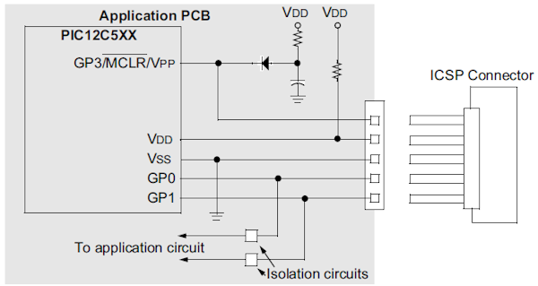
From Microchip's In-Circuit Serial Programming Guide:

enter image description here

So the diode provides \$V_{DD}\$ to the MCLR pin when the ICSP connector is not connected or when \$V_{PP}\$ isn't present. This must be a Schottky diode.


Resistor in Vdd line.
Added RM - Steven can edit as/if desired:

Reason not 100% certain but note it is shown as a resistpr or a direct connection.
On page 2-2 of the data sheet it says:

  • Interface to the Programmer
    The cable length between the programmer and the circuit is also an important factor for ICSP. If the cable between the programmer and the circuit is too long, signal reflections may occur. These reflections can momentarily cause up to twice the voltage at the end of the cable, that was sent from the programmer. This voltage can cause a latch-up. In this case, a termination resistor has to be used at the end of the signal line.
\$\endgroup\$
3
  • \$\begingroup\$ I see, what is the reason for resistor coming from Vdd to the second pin on the ICSP connector? Wouldn't you just be connecting Vdd to Vdd? Also what does the capacitor do? Would it be safe to do this without these two components? \$\endgroup\$
    – Shubham
    Commented May 9, 2012 at 11:24
  • \$\begingroup\$ @Shubham - Just guessing: Vdd on the board and from the connector may slightly differ, and connecting them without resistor would cause a high short-circuit current. The resistor prevents this. \$\endgroup\$
    – stevenvh
    Commented May 9, 2012 at 11:27
  • \$\begingroup\$ @stevenvh - See my addition to your answer. Edit as/if desired. \$\endgroup\$
    – Russell McMahon
    Commented May 9, 2012 at 11:35
6
\$\begingroup\$

Yes, it's perfectly normal to have a resistor on MCLR to Vdd, but also raise MCLR (this time in it's Vpp role) to the programming voltage during programming. I usually use 20 kΩ for that. It's a good tradeoff between being low enough impedance to not pick up noise, but high enough that most programmers out there will have no problem driving the line to the Vpp level. Note that can be up to 13 V on some PICs.

You also need to consider the current getting dumped onto the 5 V supply rail. With 13 V for Vpp, 5 V supply, and 20 kΩ pullup resistor, 400 µA will go onto the 5 V rail. If the rest of the circuit draws at least that, then there will be no problem. The power supply will just supply 400 µA less. If it's just the PIC, you may have to consider clamping the 5 V supply, using a higher pullup resistor, or putting a diode in series with the resistor. In practise most of the time 400 µA is small enough that other parts absorb the current, and most newer PICs use a lower programming voltage anyway.

For more background and general demystification of designing to in-circuit programming see my writeup at http://www.embedinc.com/picprg/icsp.htm.

\$\endgroup\$

Your Answer

By clicking “Post Your Answer”, you agree to our terms of service and acknowledge you have read our privacy policy.

Not the answer you're looking for? Browse other questions tagged or ask your own question.