2
\$\begingroup\$

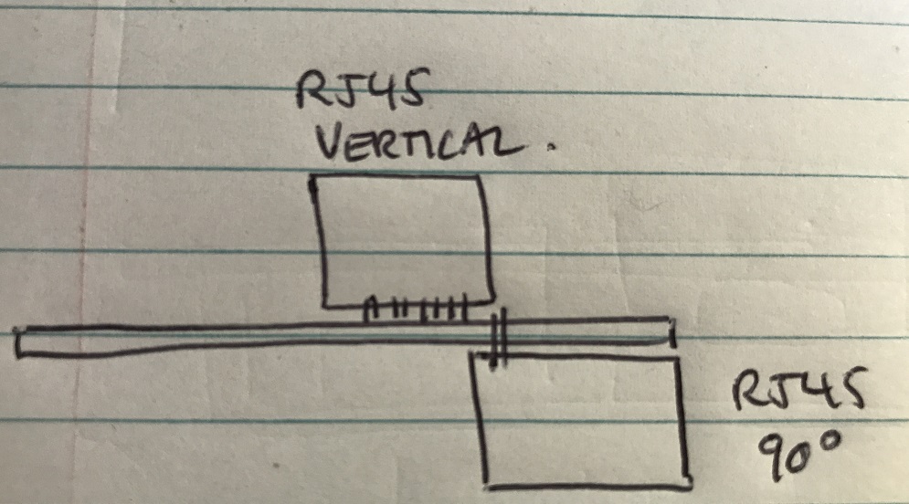
I'm doing a PCB design which includes a Gigabit Ethernet 'coupler' - i.e coupling from one CAT 5e cable to another via my PCB (see sketch below) My question is, how careful do I need to be with controlled impedance given that the PCB tracks will be quite short (in the order of 0.5") ?

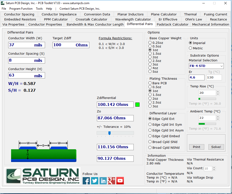
I'm hoping to get away with 2-layer, 1.6mm FR4. Using any of the online edge coupled microstrip calculators, I'm coming up with a track width of 38mil with a spacing of 8mil which is just not going to fit!

Thanks!

RJ45 coupler Microstrip calculation

\$\endgroup\$
1
  • \$\begingroup\$ Can you use a thinner PCB? That only adds a little cost. \$\endgroup\$ Commented Jul 11, 2017 at 6:49

1 Answer 1

2
\$\begingroup\$

The importante part is that you must set the rule about matching. As your data is diferential lines you must pay attention to the matching of the lines, around 100mils. If you want a more precise information many manufacturers add the routing rules in the datasheet.

Also the impedance for physical lines is 100ohms in diferential as you have it.

Another factor you should take into account is the separation between lines. This information I don't remember but check the data sheet of the connector or coupler, I'm sure they have some info about this.

Hope this information is useful. Best regards.

\$\endgroup\$

Your Answer

By clicking “Post Your Answer”, you agree to our terms of service and acknowledge you have read our privacy policy.

Not the answer you're looking for? Browse other questions tagged or ask your own question.