What I am wondering is how to build an antenna. Upon unscrewing my telescopic antenna from it's base, I see only a metal screw base, nothing more. The F Connector has a positive and negative (or ground) connector, the outside is negative and the pin in the center is positive, but I don't see how to make an antenna like this. Where do the positive and negative connectors lead to if the antenna is basically a metal stick?
-
1\$\begingroup\$ When the antenna receives a signal that it resonates to, then current will flow out of one end and in from the other. It only resonates to AC signal. A good way to think about it is as if you have an AC signal connected to a capacitor, the capacitor end that goes somewhere will push and pull current. \$\endgroup\$– Harry SvenssonCommented Jul 12, 2017 at 23:41
-
\$\begingroup\$ So would that mean that the ground is just a metal surface, and the positive connection is the antenna? \$\endgroup\$– ToastHouseCommented Jul 13, 2017 at 0:41
-
2\$\begingroup\$ We are having trouble accepting your terminology: positive and negative refer to DC, static voltages or currents. Antennas only radiate power where voltages and currents are changing (very rapidly). \$\endgroup\$– glen_geekCommented Jul 13, 2017 at 1:54
-
1\$\begingroup\$ On both ends of the antenna, one end is positive and the other negative, then they switch and the reverse happens \$\endgroup\$– Voltage Spike ♦Commented Jul 13, 2017 at 5:19
2 Answers
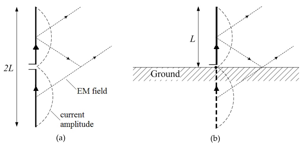
I think you might be getting confused between monopoles and dipoles: -
Look at the left picture above - it is called a dipole and it requires a balanced two wire connection. It produces and receives radio waves but, along the horizontal centre line the electric and magnetic fields are neutral and you could insert a thin horizontal conducting sheet in that plane and the operation of the dipole would be unaffected.
You can even short that conducting sheet to ground and it would still be unaffected. So then we come to the monopole (on the right). It has taken what I have said and drives just one half of the dipole arrangement with respect to earth. Do you see the difference?
A monopole requires one wire connection to the antenna and one wire to ground. The wire to ground can be very tenuous (as per a transistor radio tuned to FM) and that connection relies on the radio's 0 volt capacitance to ground to form that connection. Sounds unfeasible but it's true - do some math on what capacitance is needed and you'll figure it's true.
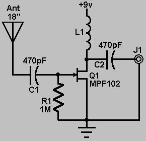
Take this schematic for an example, there is no positive or negative point on the antenna. Whenever RF arrive and resonate with the antenna, then there will be an AC voltage difference across the antenna which in turn will let current flow forward and backward through the antenna.
In the schematic below that current is connected to a capacitor so only the AC component of the antenna gets amplified.
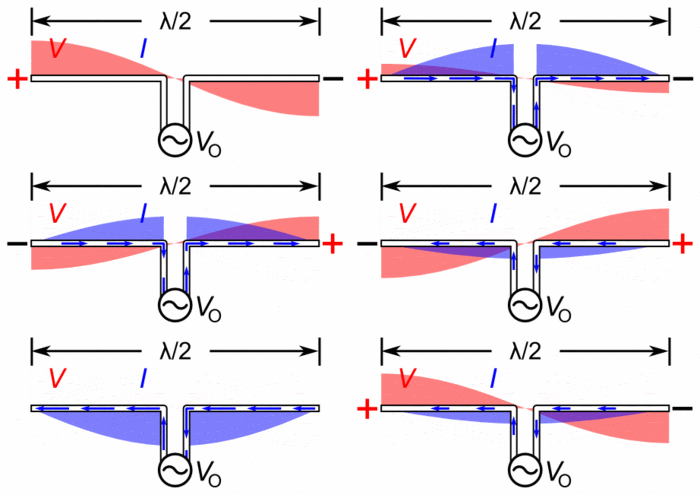
Another kind of antenna that uses two connection points called a Dipole antenna would look like this:

(source: wikimedia.org)
They are probably much easier to understand. And in this animation as well you see an AC current being forced through the center ends. There is no positive nor negative point. If you would flip the antenna horizontally, nothing would change.
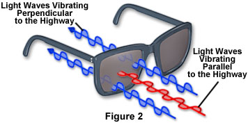
The "metal stick" you're talking about works nearly identical to the dipole antenna, only that the RF is polarized 90 degrees. That means that if you have your antenna straight up and send information, then a dipole in the orientation like the animation above won't see it. Ever.
Like these glasses:
I'm looking forward to others with way more knowledge about antennas to correct me.
But the bottom line is this, there is no positive or negative terminal, it's just AC current that you amplify and then read.
-
\$\begingroup\$ I understand how an antenna receives radio waves, but how would one be assembled? Antenna connectors always have two connections, A twin lead antenna has two wires, hence the term twin lead. An F connector still has two connections, the "negative", the part that screws on, and a "positive", the pin in the center. Telescopic antennas still have two connectors, but it is still just a metal stick. Do both connections lead to a single connection where the stick is mounted? Sorry if you don't understand. \$\endgroup\$ Commented Jul 13, 2017 at 2:37
-
1\$\begingroup\$ Woaw. Now I finally understand what you're talking about. Woaw. Okay, so the outer "Housing", the "shielding" is just like in a coax cable. An outer layer connected to ground. That is done so the whole cable doesn't work like an extension of an antenna. But no, not always is there two connections, if the base of the antenna is right next to the circuit then you wouldn't need to shield the line. But the kind of antenna you are talking about is like a coax cable with a straight metal piece connected to the inner wire. That's essentially what you got. \$\endgroup\$ Commented Jul 13, 2017 at 2:54
-
1\$\begingroup\$ Check out en.wikipedia.org/wiki/Transmission_line \$\endgroup\$ Commented Jul 13, 2017 at 2:58
-
1\$\begingroup\$ @Daniel Yes, the outer part of the SMA should be connected to ground. Otherwise the characteristic impedance will be wrong, if you don't match the impedance you will get a lot of problems (such as ringing, noise). \$\endgroup\$ Commented Jul 12, 2021 at 19:05
-
1\$\begingroup\$ @Daniel I've never worked with this so I'm only going off my gut feeling + academic knowledge. I recommend you to get a second opinion on this. - Yes the same principles applies most likely to that F connector, on the wiki page it says "It has good 75 Ω impedance match for frequencies well over 1 GHz", if you screw that impedance up and/or don't match it at the terminals you'll see a lot of ringing everywhere which will be a source of unnecessary noise (ringing and echoing). The shield should definitely be grounded, otherwise that 75 Ω impedance won't be 75 Ω. \$\endgroup\$ Commented Jul 15, 2021 at 20:18


