2
\$\begingroup\$

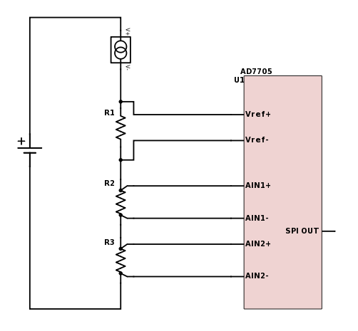
I'm working on a design which must read temperature using RTD pt100 with at least 0.5 degree Celsius accuracy in the range -10 to 50 degrees . I want to use AD7705 ADC. my design looks like this.enter image description here

I want my design to be independent of the changes in current source. that's why I used a reference resistor (R1) and fed it's voltage to ADC's reference pins. what I want to know is, shouldn't the reference pins be constant? will this configuration work? I appreciate any additional suggestions but I want the whole thing to cost less than 18$.

\$\endgroup\$
1
  • 5
    \$\begingroup\$ Does Vref+ and Vref- not set the upper and lower limits of the ADC? If so your AINs are all below the minimum. \$\endgroup\$
    – Transistor
    Commented Aug 20, 2017 at 21:34

4 Answers 4

2
\$\begingroup\$

Page 5 of the data sheet (https://www.analog.com/media/en/technical-documentation/data-sheets/AD7705_7706.pdf) specifies that the Analog in range is \$\frac{\pm V_{REF}}{\textrm{gain}}\$ for bipoolar setup, so your input scheme isn't correct. Your input voltages are out of range.

\$\endgroup\$
1
\$\begingroup\$

Your design requires surge currents, as the ADC grabs charge for the conversion behavior. Thus the resistors, along with parasitic capacitance, need to implement a fast timeconstant, fast enough to settle to at least 0.5 degree C during the sampling interval and also during the grab-some-reference-charge as each bit of the successive-approximation-conversion occurs.

One Tau of settling provides 8.6dB improvement in measurement. Thus 10 tau, provides 86dB accuracy (other errors also exist; you must identify and manage those other errors), or nearly 13 bits.

By the way one Tau settling is NEPER.

\$\endgroup\$
1
\$\begingroup\$

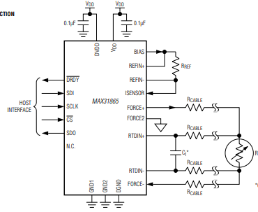
Use the chip MAX31865 instead.

I've been using with great success to measure PT100, the chip takes care of everything and is very easy to implement.

You only need to power the chip and provide a reference resistor, you don't need to care about anything how to drive the RTD.

It also does wire compensation (3 or 4 wire RTD) and some other internal compensation.

Total BOM cost is about 5$ all included.

enter image description here

\$\endgroup\$
1
\$\begingroup\$

In general, what you're trying to do is to have ratiometric operation. That's good. You just over-complicated the design somewhat. It works in principle, just not with the particular chip you chose - and may not work with any ADC for that matter. But if all ADCs had fully differential, wide-common-mode reference voltage inputs, it'd have worked all right!

For ratiometric operation, you could use a fixed voltage. So there's no need to convert current to voltage. Power the PT100 half-bridge from a fixed voltage and that's all. You also have a choice in whether to measure each resistor separately or both together on the 2nd channel. Or you could measure the total voltage across the circuit as the reference voltage. It'd do the same thing. You still have an accurate current measurement from the reference ("fixed") resistor.
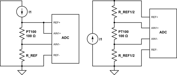
schematic

simulate this circuit – Schematic created using CircuitLab

Both approaches above perform reasonably, depending on what reference voltage range the ADC accepts. The 2nd circuit places the input common mode in the middle of the reference. Most high resolution ADCs perform well in that scenario. The trade-off is needing two reference resistors instead of just one.
\$\endgroup\$

Your Answer

By clicking “Post Your Answer”, you agree to our terms of service and acknowledge you have read our privacy policy.

Not the answer you're looking for? Browse other questions tagged or ask your own question.