1
\$\begingroup\$

So I have some old dynamo, and I want it to power my GPS navigator.

But first of all I want to calculate its maximum power it can deliver.

Setup: two wires are soldered to dynamo on one end, on other end they are soldered to 5 Ohm resistor. True RMS multimeter is measuring AC voltage across the resistor.

Results: on my normal speed it showed 3 V. On my maximum speed 3.15 V.

3*3/5 = 1.8 W

Dynamo is labeled 3 W, measured resistance 33 Ohm.

The copper wires are near 0 Ohm. All joints are soldered. There cannot be any losses.

Question 1: Did I do right to calculate maximum dynamo's power?

Question 2: Where is 1 W lost?

\$\endgroup\$
1
  • \$\begingroup\$ The 3W marking is a very approximate rating. Why did you use 5 ohms as the load? As @jasen describes in his answer you need to match the load to the generator to get maximum power. This optimum load will change with RPM. \$\endgroup\$ Commented Aug 26, 2017 at 20:53

2 Answers 2

3
\$\begingroup\$

Dynamos are inherently current-limited.

The current limit is because the permanent magnet has a fixed magnetic strength this places a limit on the current it can induce in the dynamo windings.

There is no voltage limit, the faster you ride the more open-circuit voltage the dynamo will provide.

To get more power out use a higher resistance (and ride faster) maximum output will be by matching the dynamo resistance and riding at extreme speed, maximum practical output will likely be somewhat lower.

to get closer to 3W output try 8 ohms.

\$\endgroup\$
6
  • \$\begingroup\$ The current limiting is not due to the fixed magnetic strength but the inductance of the windings. As the RPM increases the induced voltage increases but the frequency and hence the reactance of the winding inductance also increases. \$\endgroup\$ Commented Aug 26, 2017 at 20:50
  • \$\begingroup\$ But am I calculating it right? I mean did I really get power output? How did you get 8 Ohms? \$\endgroup\$
    – Qeeet
    Commented Aug 26, 2017 at 21:01
  • \$\begingroup\$ @KevinWhite that's just a more complicated way of looking at the same thing, \$\endgroup\$ Commented Aug 26, 2017 at 21:06
  • \$\begingroup\$ @Qeeet, your calculation is correct, I get 8 by seeing that the current the dynamo produces gets you about 2/3 of what you expect, so by increasing the resistor by about half you should get you more voltage at the same current. \$\endgroup\$ Commented Aug 26, 2017 at 21:09
  • \$\begingroup\$ You were right. I've put 10 Ohm resistor and I got 5.75 V at my maximum speed. That is 3.3 W. Damn, I see it is a big deal to get 5 V @ at least 0.3 A out of it \$\endgroup\$
    – Qeeet
    Commented Aug 26, 2017 at 22:15
4
\$\begingroup\$

Inductive voltage regulation

The traditional bicycle dynamo's (see note) output voltage will vary roughly proportional to speed. If this problem is not addressed the lamps - its intended load - will be very poor at low speeds and the bulbs will blow at high speed. The solution is to design the system - dynamo and lights - as a complete package with enough series inductance built in to the dynamo to regulate the terminal voltage.

Note: Technically the bicycle generator is an alternator since it outputs AC. Dynamos output DC.

schematic

simulate this circuit – Schematic created using CircuitLab

Figure 1. Standard dynamo arrangement showing internal series resistance and inductance.

The impedance of an inductor is given by \$ Z = 2 \omega L = 2 \pi f L \$. This shows that the impedance is proportional to the frequency which, of course, is directly related to the speed of the bike. If designed correctly the lamps will turn on to a reasonable brightness at quite low speed and will be noticeably brighter at high speed but without blowing the lamps - the reason being that the inductors and lamps form an L-R voltage divider.

Setup: two wires are soldered to dynamo on one end, on other end they are soldered to 5 Ohm resistor. True RMS multimeter is measuring AC voltage across the resistor.

Since the specification is 3 W at 6 V we can calculate from \$ P = \frac {V^2}{R} \$ that optimal load is given by \$ R = \frac {V^2}{P} = \frac {6^2}{3} = 12 \; \Omega \$.

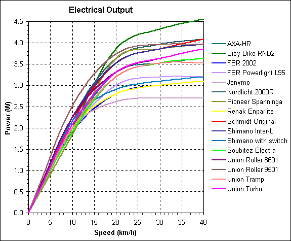
If that works you might wish to chart power as a function of velocity. It should be fairly constant.

There are various articles on the web from folks who have tried to figure out the characteristics of various alternators.
enter image description here

Figure 2. Comparison of various brands and models as a function of speed. Note that the load is not specified. It can be assumed that it is the same 2.4 + 0.6 W front and rear bulb configuration. Source: Myra-Simon.

\$\endgroup\$
3
  • \$\begingroup\$ Car alternators use the same technique of current limiting. \$\endgroup\$ Commented Aug 26, 2017 at 22:55
  • \$\begingroup\$ There's a 2 in excess, and a missing | | or j. \$\endgroup\$ Commented Mar 23, 2021 at 1:59
  • \$\begingroup\$ Load is described in this way: Cycle light bulbs etc. are insufficiently reliable for test purposes, so voltage was measured across a high quality 12 ohm resistor (1%, 50W) with parallel 7.8 volt Zener diodes (BZW7V8B). These components model the usual kind of 6V, 3W dynamo lighting system, with which all the generators tested were intended to be used. \$\endgroup\$ Commented Mar 17 at 16:24

Your Answer

By clicking “Post Your Answer”, you agree to our terms of service and acknowledge you have read our privacy policy.

Not the answer you're looking for? Browse other questions tagged or ask your own question.