4
\$\begingroup\$

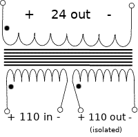
Given a transformer with a dual primary winding (generally used to step down a series 220v or paralel 110v), can I instead hook up one winding to a 110v input and use the second as an isolated 110v output?

Diagram of transformer connections

What kind of power restrictions or undesired behavior might this cause?

EDIT: This transformer, for example: http://mouser.com/ds/2/410/media-1067445.pdf

EDIT2: Added 24v to the image secondary coil for clarity

\$\endgroup\$
7
  • 1
    \$\begingroup\$ Yes, at half the rated power of the transformer (because you normally split the power across both primaries). The secondary will provide slightly lower voltage once you subtract all the internal losses. \$\endgroup\$
    – user16324
    Commented Aug 27, 2017 at 21:50
  • \$\begingroup\$ If you have the full datasheet for the transformer, could you post it please? \$\endgroup\$ Commented Aug 27, 2017 at 21:52
  • \$\begingroup\$ I'm thinking theoretically, but this would be a good candidate for my application: mouser.com/ds/2/410/media-1067445.pdf \$\endgroup\$
    – cjgriscom
    Commented Aug 27, 2017 at 21:53
  • 1
    \$\begingroup\$ Just note that Note 4 on the transformer data sheet says that the windings, both primary and secondary, are designed to be used in either series or parallel but not independently. \$\endgroup\$
    – Barry
    Commented Aug 27, 2017 at 22:40
  • \$\begingroup\$ Then doing so would violate the labeling and instructions of the device, and is disallowed. Or you could just buy an isolation transformer. \$\endgroup\$ Commented Aug 28, 2017 at 3:20

3 Answers 3

10
\$\begingroup\$

You can if you only need functional isolation. If safety isolation is required you need a transformer designed for that.

Since you are only powering half the primary you can only put in half of the primary current so you only get half the VA rating of the transformer, so compared to a real isolating transformer you end up with twice as much iron and an unused secondary.

Safety: These units are designed with 4000VAC isolation between the primary and secondary, and also,between each winding and the core.

If there had been a comma after "winding" it would be a different story, as it is there's probably only about 250V isolation between the two secondaries, they may well be wound bifiliar (intermixed)

\$\endgroup\$
1
  • \$\begingroup\$ Nice point on the absent comma. As your point indicates - There is (probably) a lack of spec on the p1:p2 isolation but this note could easily be read as if it just that. \$\endgroup\$
    – Russell McMahon
    Commented Aug 28, 2017 at 1:11
3
\$\begingroup\$

If you are planning on using the isolated primary to do something like supplying Nixie tubes, and the secondary supplies the logic, and safety depends on mains isolation of both, I would not suggest using this kind of transformer. It will work, but it will not have adequate isolation for safety.

There are dual split-bobbin construction transformers and they would be much better, but I suggest checking with the manufacturer to see if they Hipot test between primaries and if they would recommend this service.

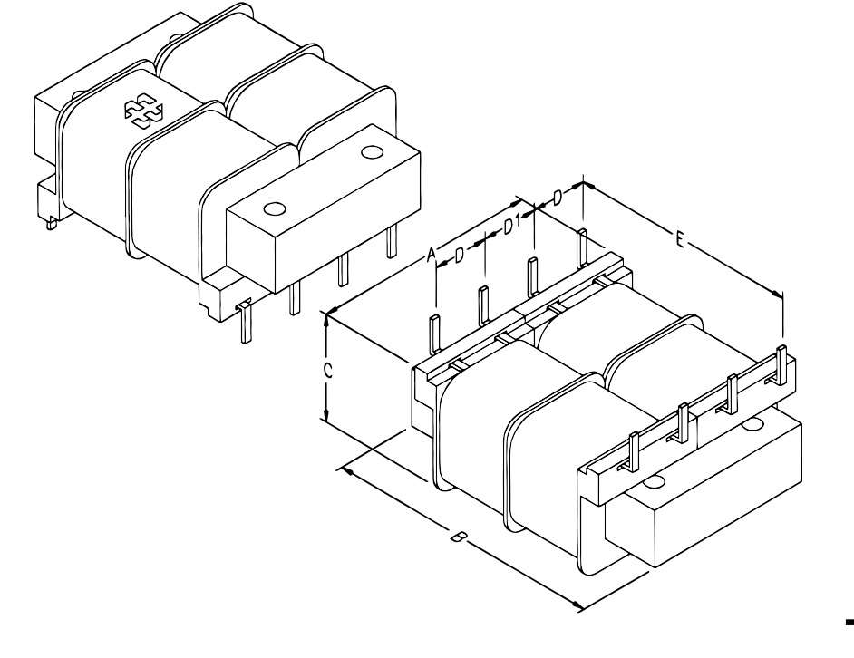
The below illustration is from a Hammond 229A12 6VA part:

enter image description here

As you can see, each coil is independently isolated by the bobbin structure.

\$\endgroup\$
3
  • 1
    \$\begingroup\$ I am indeed using this for a tube project (audio) with the secondary for regulatory circuits. I think I understand the safety issue and may consider the split bobbin or perhaps two separate transformers. \$\endgroup\$
    – cjgriscom
    Commented Aug 29, 2017 at 4:20
  • \$\begingroup\$ if they hi-pot between the windings and the core, there should be the same or better isolation between each side. I would expect more magnetic radiation when used like this \$\endgroup\$ Commented Aug 30, 2017 at 0:00
  • 1
    \$\begingroup\$ @Jasen Split-bobbin transformers have more leakage inductance, yes. Ideally (magnetically) you would interleave primary and secondary but that's not safe unless you use special wire. \$\endgroup\$ Commented Aug 30, 2017 at 3:40
0
\$\begingroup\$

Why not connect the two "110" windings in series? (Do observe polarity - connect the "dotted" lead of one to the "not dotted" of the other.)

Then apply 110 across the two of them, and you get 110 out, isolated, across the "220" secondary. Or turn it around: Put 110 into the "220" winding and you'll get 110 out across the pair of series windings.

110V in, 110V out, and no loss in rated power.

There is no rule that says that a "220" winding absolutely must be operated with 220 across it.

\$\endgroup\$
3
  • \$\begingroup\$ the linked part does not have a 220V secondary. (it's 2 x 12V) \$\endgroup\$ Commented Aug 29, 2017 at 23:57
  • \$\begingroup\$ I saw that. I'm assuming the transformer the OP wants to use is as the OP drew the diagram. \$\endgroup\$ Commented Aug 30, 2017 at 8:03
  • \$\begingroup\$ Seems the OP edited the diagram since my "answer". :) \$\endgroup\$ Commented Nov 4, 2018 at 17:40

Your Answer

By clicking “Post Your Answer”, you agree to our terms of service and acknowledge you have read our privacy policy.

Not the answer you're looking for? Browse other questions tagged or ask your own question.