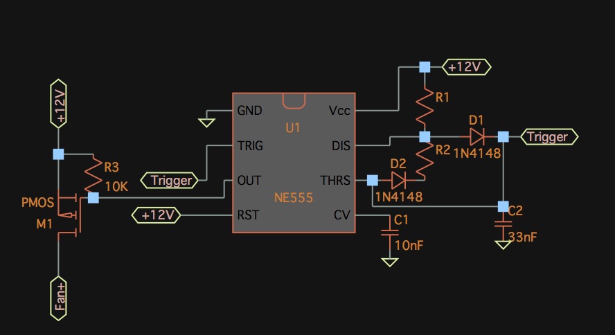
The short answer is: no. There is no way to make an increase in the resistance of the top (R1) resistor in the discharge/trigger divider result in a decrease in duty cycle on the 555's output pin, or vice versa.
Why is it so important to have the sensor take the place of R1? If you simply use it as R2, then duty cycle will increase as R2/the sensor's resistance decreases, and it will decrease as the sensor's resistance increases.
Assuming you're using the standard 555 Astable PWM circuit that makes use of two diodes to permit duty cycles lower than 50%, you can figure out what resistance you need knowing that the duty is \$D=\frac{R1}{R1+R2}\$.
If you absolutely must use the temperature sensor as R1, then your only other option is to invert the output of the 555's output pin. This will effectively turn the duty cycle from % of time spent on to % of time spent off. You could achieve this fairly simply by making the output pin drive a P-channel MOSFET, with the gate connected to the 555's output pin (and you probably want a pull-up resistor from the gate to 12V as well), connect the FET's source to 12V, and connect the positive input of the fan to the drain of the FET. The P-channel FET will be off when there is 12V at the gate, and will only turn on when the 555's output is low and pulls the gate down. Conveniently, 12V on the gate is pretty much ideal to fully turn on any MOSFET, so no worries there.
Something like this, which would have a PWM frequency of ~1.2kHz or so: 

