0
\$\begingroup\$

I guess you might think that this question has been asked before, but what I need to ask is something very different.

I have RN-131 which is a wifi module from Roving Networks and also
RN-SRL-PRO3V-DGL which is a USB to TTL dongle - datasheet here which connects to the wifi module through UART. The connections I made between the wifi module and the dongle are:

TX(dongle) ------ 100ohm resistor ------- RX(wifi module)

RX(dongle) ------ 100ohm resistor ------- TX(wifi module)

GND(dongle) --------------- GND(wifi module) [here dashes mean wires]

Now I can communicate with the wifi module through TCP by putting the module into ADHOC module. Whatever the module receives over wifi is received by its UART and whatever is written to its UART is transmitted over wifi.

Now when I connect the module to the dongle and plug the dongle into USB port of my laptop, and I use telnet's serial port. Whatever I type on telnet is not displayed. Also to program the module using UART I have to use an escape code which is $ $ $ (i put spaces cauz then text changes). I see that when I type in $$$ into telnet I dont get CMD back from the module which its supposed to when it enteres command mode. Also I receive all sort of rubbish from the module when the USB is plugged in. THere are more strange things happening which I can tell if anyone's interested

Can anyone tell me where I'm going wrong? I have been trying this for past 3 weeks but couldn't get anywhere. What am I supposed to do?

\$\endgroup\$
12
  • \$\begingroup\$ Have you got the baud rate and handshaking set correctly? \$\endgroup\$
    – Oli Glaser
    Commented Jun 12, 2012 at 6:25
  • \$\begingroup\$ Are you sure you don't have the TX-RX lines swapped? \$\endgroup\$
    – W5VO
    Commented Jun 12, 2012 at 6:30
  • \$\begingroup\$ @Oli - the module is set to no flow control and so is my COM port. I dont want to use CTS and RTS pins, hence no flow control. That is what flow control means right? \$\endgroup\$ Commented Jun 12, 2012 at 6:33
  • \$\begingroup\$ @W5VO - Im 100% sure that I have connected Rx of dongle is connected to Tx of module and vice versa. What does Vcc on the dongle mean? \$\endgroup\$ Commented Jun 12, 2012 at 6:34
  • \$\begingroup\$ @David - yes that's what flow control is. You might want to check the module datasheet to see if it is expecting flow control to be turned on. Vcc means the positive supply rail (e.g. something like +5V, +3.3V, etc) If you don't have this connected then it won't do anything. \$\endgroup\$
    – Oli Glaser
    Commented Jun 12, 2012 at 6:39

1 Answer 1

1
\$\begingroup\$

Postscript:

A closer look at the WiFi module circuit diagram indicates that what I have written below MAY be incorrect. Rather than delete it for now until I can look into it further I'll leave it for David to look at as it MAY be useful.

Others may ignore it :-).
I'll try and get back to it later and David may have commented by then.
Work calls ... ;-)

Note that WiFi RXDIN connects to SENS0 on pin 34 and also to URX on pin 12.
This may allow some form of level detect and shift.

References at end should be useful.


  • Based on available data sheets and manual, you appear to have an RS232 level incompatibility issue. The WiFi module is using +/- 10 data signals. The USB-UART dongle is using 3V3 or 5V data signals.

  • There is probably an inverted polarity issue as well.
    Given the voltage levels used in each case:

  • The WiFi module probably uses inverted logic levels

    where negative output / DC low / V- = logic 1 = logical high,

  • The USB-UART dongle probably uses standard logic levels

    where positive out / V+ = logic 1 = logical high.

If this is what is happening it would explain what you are seeing.
The WiFi unit sees inverted (to it) polarity signals at a level which may or may mot always trigger it's input gates. When it does respond it outputs signals which are inverted in polarity to what the dongle expects and at excessive voltage levels.

The above is easily enough checked by measuring the voltage on TX out at the connectors in each case with the devices not connected to each other.
WiFi module TX out idle

Data sources listed at end.

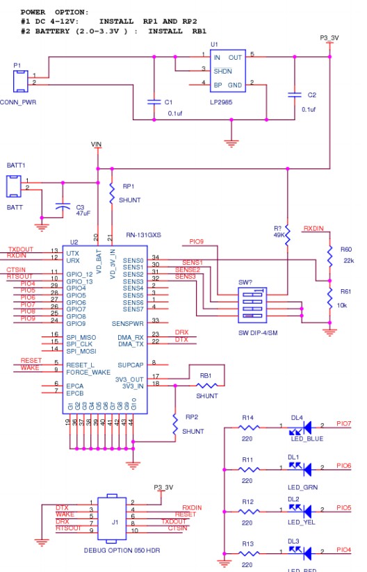
The diagram below is for the "Roving Networks RN131G WiFi module".
Assuming that it is the same as your RN131 -

External data in line = RXDINJ (as shown on diagram below)
Data in at IC U2 = RXDU2 (called SENS0 on diagram)

The IC U2 operates from 3V3.
The RXDIN line at right middle has a 22k/10k R60/R61 voltage divider.
This gives a 3.2:1 division of the data signal.
If data high is expected to be no more than 3v3 at RXDU2 on IC U2 then this allows an up to
3.2 x 3v3 = 10.6V data signal on RXDIN.
If the IC accepts Data_in_high of as low as say 70% of Vdd then minimum data in at the IC U2 = 3v3 x 70% =~ 2.3V.
To achieve 2.3V minimum at the IC would require a RXDIN data in signal of
3.2 x 2.3V = 7.4V.

As the USB-UART interface dongle expects a 3v3 "TTL" interface (or 5V depending which datasheet line you read) it will not each a valid

c:\zzz\RN131G WiFi moduleenter image description here

Dongle datasheet

Dongle sold here by Mouser

They say

  • ... The RoHS compliant PCB assembly is configured with a fixed TTL output level of +3.3V.

    Deriving its power from the USB bus connection, ...

RN-SRL-PRO3V-DGL: USB to 3V serial UART dongle, Prolific chipset, USB connector, bare PCB 5V serial
connection

More soon ...

\$\endgroup\$
4
  • \$\begingroup\$ wow that was really detailed, RN-131 TX pin is active low, so when idle (while its not receiving anything through wifi) the TX pin would be high (i.e. at 3.3V). Also I dont really get why the Voltage divider is necessary at SEN0. I had seen that earlier but I thought that was to wake the module up from sleep upon Receiving data. But I have noticed when I plug the dongle in my USB port (note, at this point the wifi module is also powered up), the voltage on TX pin of the dongle has a voltage drop of 0.72V, even when I send something through terminal emulator, 0.72V is stationary. \$\endgroup\$ Commented Jun 12, 2012 at 21:55
  • \$\begingroup\$ Also I should point out, I wanted to check if the UART (TX-RX pins) are working fine on RN-131, So I used an oscilloscope to observe the TX pin only. When I send a string say for example "Hello World" I see the TX pin go 'low' while it receives data over wifi. As you might already know, whatever RN-131 receives over wifi is transmitted out its TX pin and whatever is received on its RX pin from UART is transmitted out wifi. You reckon this is a good way to test RN-131??? \$\endgroup\$ Commented Jun 12, 2012 at 21:58
  • \$\begingroup\$ @DavidNorman - Sounds correct. WiFi module serial TX to dongle should be high when idle. Dongle TX to WiFi should be high when idle. Presumably you have set equal baud rates in some manner or they default to the same value? Voltage levels at both ends should be the same 5V and 3V3 are liable to sort of work maybe not. \$\endgroup\$
    – Russell McMahon
    Commented Jun 13, 2012 at 2:19
  • \$\begingroup\$ The baudrate on the wifi module is set by default (which is 9600bps, 8-data bits, 1-stop bit, no parity, hardware flow disabled. What if I loopback TX into RX would that damage the module? This would be to see whatever message I send from the source through wifi will be bounced back to the source? You reckon the module should be find if I do so? I contacted Roving about this, its been 3 days they haven't replied. \$\endgroup\$ Commented Jun 13, 2012 at 3:04

Your Answer

By clicking “Post Your Answer”, you agree to our terms of service and acknowledge you have read our privacy policy.

Not the answer you're looking for? Browse other questions tagged or ask your own question.