1
\$\begingroup\$

I want to obtain the inductance value from a coil. To do so i'm using a basic RL circuit as follows. The function generator has a 50 Ω internal resistance and the coil resistance is 87 Ω. The coil has a small sticker with it's value (6,24 mH) supposedly provided by the manufacturer. I would like to prove it experimentally to be sure that it's correct.
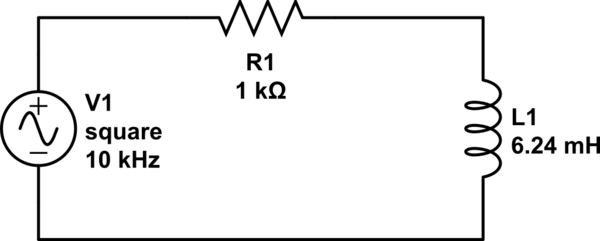
schematic

simulate this circuit – Schematic created using CircuitLab

As we know the voltage that goes through the coil tends to 0 following this expression: \$V_{L}(t)\$=V·\$e^{-t/τ}\$, where $$τ=\frac{L_{1}}{R}$$
What I was doing with the oscilloscope was taking the difference of time between the signal rising start and the moment where the exponential is the 36.79% of the initial value. Then considering this number τ and knowing R value I calculated L1 (L1=R·τ). The result is not the expected and I firmly believe that this method is not correct at all.

What I tried next was similar, taking two points but this time the first one is a little bit after the maximum voltage and the second the 36.79% of the first one. Now with the time and voltage difference between the two instants and the expression seen before I calculated $$L_{1}=\frac{-(t_{2}-t_{1})·R}{ln(\frac{V_{L}(t_{2}-t_{1})}{V})}$$ Again the result is not correct.

I would like to know what i'm doing wrong.

Anyway if you know a different and simple way to measure the inductance experimentally i'm open to sugestions.

Thanks!

\$\endgroup\$
1

2 Answers 2

0
\$\begingroup\$

schematic

simulate this circuit – Schematic created using CircuitLab

Figure 1. (a) Interpretation of original post. (b) Improved measurement technique?

I can't quite figure out how you are taking your measurement but I suspect it is as shown in (a). This has the disadvantage that you are measuring the voltage drop across the internal resistance.

(b) shows an alternative approach: measure the current through the inductor. By using your 1k as a current shunt you should see the voltage across R4 follow an exponential rise curve. When the driving voltage goes positive you should measure the the rise time to 1- 36.79% = 63.21% of the final voltage.

\$\endgroup\$
1
  • \$\begingroup\$ Your suspicion is true, figure 1.(a) shows how I was measuring. I'll try 1.(b). Thanks. \$\endgroup\$
    – PJC
    Commented Nov 2, 2017 at 23:04
1
\$\begingroup\$

If you don't have a model number and a datasheet then there is no use comparing it to the value listed on the inductor because the value of the inductance is not the only thing that can define the properties of a non-ideal inductor. There are a few things that can change the measured value:

1) Parasitics
2) Self resonance
3) Core material

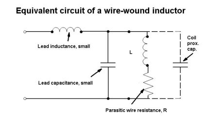
Parasitics - A real inductor has internal capacitance between coils and wire resistance, depending on the construction and especially at higher frequencies these can change your results of measuring inductance drastically. ESR can also be a big factor (the resistance from the coil of wire)

enter image description here

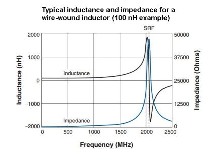
Self resonance - Because of parasitics (and other parasitics in your circuit) there can be a self resonance point, if your measuring near it it will throw off the value of inductance/impedance your measuring

enter image description here
Source of both pictures: Analog tips

Core materials - If the core is not an air core but made of ferrite or some other material this will change the measured value of inductance. Ferrous materials exhibit hysteresis and will cause your signal to saturate. Ferrous materials in a core will make things difficult to measure and model.

What can you do about it? First of all, use more than one frequency, and scan several frequencies and plot it as in the chart above. Depending on the value of the inductor, run a range of frequencies 1Hz 10Hz 100Hz 1kHz 10kHz 100kHz and 1MHz. (after 10Mhz parasitics will usually take over unless they are controlled/eliminated)

Account for the ESR, if your coil is large you can measure it and incorporate it into your equation.

\$\endgroup\$
2
  • \$\begingroup\$ I did not take into account this things you point out. Thanks. \$\endgroup\$
    – PJC
    Commented Nov 2, 2017 at 23:01
  • \$\begingroup\$ No need to say thanks, just mark the most helpful answer \$\endgroup\$
    – Voltage Spike
    Commented Nov 2, 2017 at 23:12

Your Answer

By clicking “Post Your Answer”, you agree to our terms of service and acknowledge you have read our privacy policy.

Not the answer you're looking for? Browse other questions tagged or ask your own question.