-4
\$\begingroup\$

In the circuit below the switch is open and the capacitor starts with an initial energy of 0J and an initial potential of 0V in it.

The switch is closed and both the battery and the inductor's magnetic field charges the capacitor up. Everything then settles down and comes to a full rest.


The Question is: Once the process is complete after the closing of the switch and everything is settled down and has come to rest, How much energy in the form of joules should the capacitor have in it as well as how much voltage should the capacitor be charged up to?

This is a real world circuit with losses in the battery source, the connecting wires, the switch, the capacitor, the diode and the inductor. So not a perfect circuit by any means.

There is no inductance value, and in fact several different types of coil sizes and resistances were tried with the same result, so that's the reason for leaving off the inductance value. The inductance value is not 0 nor is the resistance value 0.

The answer doesn't have to be exact and just a general answer is expected. If the inductance somehow changes the answer to different answers then just include an inductance of some value, just as long as it's not 0H.
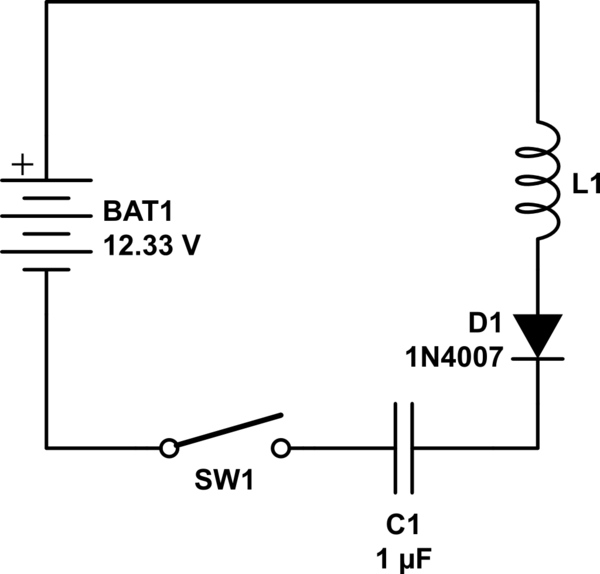
schematic

simulate this circuit – Schematic created using CircuitLab

\$\endgroup\$
12
  • 1
    \$\begingroup\$ See this question : electronics.stackexchange.com/q/337693/152903 \$\endgroup\$
    – Solar Mike
    Commented Nov 3, 2017 at 18:46
  • 1
    \$\begingroup\$ Given the excellent answers you have already been given, you should be able to include the effect of the diode... \$\endgroup\$
    – Solar Mike
    Commented Nov 3, 2017 at 18:50
  • 3
    \$\begingroup\$ @MarcStriebeck what's your vote? What would it be? \$\endgroup\$
    – Deep
    Commented Nov 3, 2017 at 19:06
  • 2
    \$\begingroup\$ 😂 Wow.. congratulations for your beyond spectacular results \$\endgroup\$
    – Deep
    Commented Nov 3, 2017 at 19:12
  • 2
    \$\begingroup\$ @MarcStriebeck You've asked three questions, but what is your point? Your not going to store any reasonable amount of energy in a capacitor, thats why we use batteries. The capacitors that are used for energy storage are hybrids between batteries and capacitors (they store energy via chemical or other means). If your testing these circuits and coming up with something different, then why don't you include that in the qeustion. Instead of asking three questions ask one \$\endgroup\$
    – Voltage Spike
    Commented Nov 3, 2017 at 22:11

4 Answers 4

6
\$\begingroup\$

The capacitor will end up with approximately twice the voltage of the battery.

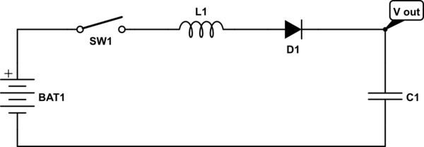
I've redrawn the circuit to make it easier to understand. It is the same circuit but with common terminal at the bottom.

With the capacitor initially discharged when the switch is closed current will flow through the inductor and diode charging up the capacitor.

The current flowing through the inductor will create a magnetic field within the inductor which will keep increasing until the capacitor voltage reaches the battery voltage.

At that point the energy in the inductor will be equal to that within the capacitor.

The magnetic field in the inductor will then start collapsing and will keep the current flowing and charing the capacitor. This will be maintained until the magnetic field is zero and all of the energy has been transferred to the capacitor.

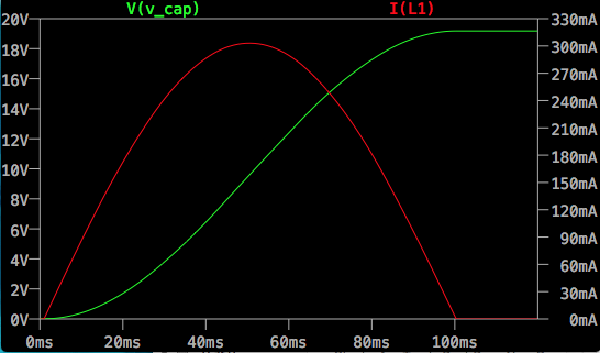
The current in the inductor and the voltage on the capacitor will be a half-sine wave. The diode will prevent any reverse current so the process will end when the capacitor reaches its peak voltage with the current in the inductor at zero.

The final voltage on the capacitor will be almost twice that of the battery.

This type of circuit was first used in WW2 radars for energizing the magnetrons and the horizontal output stage of CRT televisions and monitors also exploit this arrangement to recover energy from the scanning coils to reduce power requirements.

schematic

simulate this circuit – Schematic created using CircuitLab
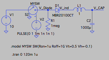
Here is an LTSPICE simulation of the circuit. The green trace is the voltage on the capacitor, the red trace is the current in the inductor. Notice that with real components the voltage doesn't quite reach twice the 10V of the battery.

Cap charging plot

And the LTSPICE schematic

Cap charging schematic

\$\endgroup\$
8
  • 1
    \$\begingroup\$ There was no need to change the circuit, it's the exact same thing, anyways, If the capacitor was charged to twice the voltage of the battery, that would be 24.66 V and there would be 304.058 uJoules of energy in the capacitor. If there was just a battery and a capacitor only then only 50% of the energy would make it into the capacitor which is only 76.014 uJoules. Twice that would be 152.028 uJoules of energy which is a whopping 100%. Here you're saying that there is 304.058 uJoules of energy in the capacitor at 24.66 V. Something is horribly wrong, either in your answer or elsewhere. \$\endgroup\$ Commented Nov 3, 2017 at 20:01
  • \$\begingroup\$ I think I must be missing a fundamental rule of physics and electronics in order to conclude that if 50% of the energy is stored in a capacitor when directly connected to a battery, and then to be told that 4 times the amount of energy ends up in a capacitor from the battery with an inductor and diode, then I must be delusional or something right? This possibly can't be 200% efficient, what am I missing here? \$\endgroup\$ Commented Nov 3, 2017 at 20:09
  • 2
    \$\begingroup\$ Conservation of energy is not violated: more energy is drawn from the battery. You've effectively charged it from a boost converter. \$\endgroup\$
    – pjc50
    Commented Nov 3, 2017 at 20:29
  • 1
    \$\begingroup\$ @pjc50 - Still quite doesn't make sense. I can understand that the coil would be charging the capacitor up and then discharging the battery down because it's opposite to the capacitor's polarity. Is this an accurate interpretation? \$\endgroup\$ Commented Nov 3, 2017 at 20:44
  • 2
    \$\begingroup\$ Really you have to think of it in dI/dT terms. The current starts at zero and increases. Increasing the current moves energy into the magnetic field. In order to reach a steady state the current will have to decrease again. Decreasing the current moves energy out of the inductor in the same direction as the current. You have to either do the calculus or run it at very low speed in a simulator to see what's going on. \$\endgroup\$
    – pjc50
    Commented Nov 3, 2017 at 21:09
1
\$\begingroup\$

In re "boost converter", with this small modification to the circuit and moving the switch backwards and forwards at the right rate, you can charge the capacitor to any voltage! This probably ought to be a comment but you can't put circuits in comments.

(All components have arbitary default values)

schematic

simulate this circuit – Schematic created using CircuitLab
\$\endgroup\$
0
\$\begingroup\$

Without a diode:

At T=0, the whole system will have \$\frac{1}{2}CV^2\$ J in the form of AC, and equally much in the form of DC. The total energy in the system will be \$CV^2\$ J.

With a diode:

At T=0, the same thing can be said as without the diode, \$CV^2\$ J will be in the system in the form of AC and DC.

At some other T when all the AC has been converted into DC, you will have twice the voltage across your capacitor as you are feeding the capacitor with. So if you are feeding it with 5 V you will get 10 V across the capacitor's terminals. Or if you are using 12.33 V you will get 24.66 V.

Let's calculate the energy stored in the capacitor to see if it violates any conservative laws.

Energy at T=0: \$CV^2\$

Energy at T=(only DC): \$\frac{1}{2}C(2V)^2\$ = \$\frac{1}{2}C4V^2\$ = \$2CV^2\$

Hmm... they don't match..... they should.... this isn't how I planned this answer to end... I'll still leave this here so people with more knowledge than me can see Marc Striebeck question in another perspective.


It looks like there should be something like \$\sqrt2\$ in order for the energies to match...

lo and behold. the RMS value for a 1 V sinusoid is \$\frac{1}{\sqrt2}\$ V.

So maybe... at T=0 the energy in the circuit looks like this:

DC: \$\frac{1}{2}CV^2\$
AC: \$\frac{1}{2}CV^2\frac{1}{\sqrt2}\$

Hmmm... no I don't know where I'm going with this. I call quits on this question that gives me headache.

\$\endgroup\$
-1
\$\begingroup\$

This is actually quite a funny circuit, but if you use real components and realy wait for the steady state, the C will be charged to the battery voltage, no more and no less.

If you use ideal components (especially an ideal diode without reverse leakage), the C will be charged higher than the battery voltage. But with a non-ideal diode this extra voltage will leak away over time.

\$\endgroup\$
1
  • \$\begingroup\$ You're right it is quite a funny circuit isn't? What I probably should have asked is what is the voltage on the capacitor before it begins to drop to discharge the battery for the second time. Do you mind telling me what that might be or what would the highest possible voltage be? 24.66V? \$\endgroup\$ Commented Nov 3, 2017 at 21:27

Not the answer you're looking for? Browse other questions tagged or ask your own question.