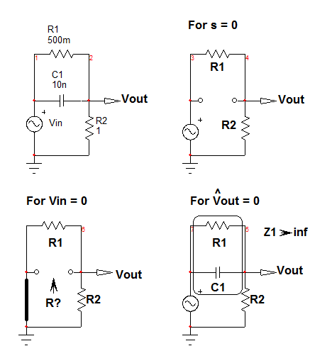
If we assume the system offers a resistive loading your circuit, \$R_2\$, then yes, it looks like a band-pass filter featuring a zero and a pole. The transfer function of such simple 1st-order circuit (1 energy-storing element, capacitor \$C_1\$) can be determined using the FACTs without writing a line of algebra. First, draw the circuit for \$s=0\$: open the cap, the transfer function is given by the resistive divider: \$H_0=\frac{R_2}{R_1+R_2}\$.
Now, reduce the excitation voltage to 0: replace the input voltage source by a short circuit and "look" at the resistance offered by the capacitor's connecting terminals when it is temporarily removed from the circuit. If you look at the below sketch, you see \$R_1||R_2\$ and the first time constant \$\tau_1=C_1(R_1||R_2)\$. In a 1st-order circuit, the pole is the inverse of the time constant thus: \$\omega_p=\frac{1}{C_1(R_1||R_2)}\$.

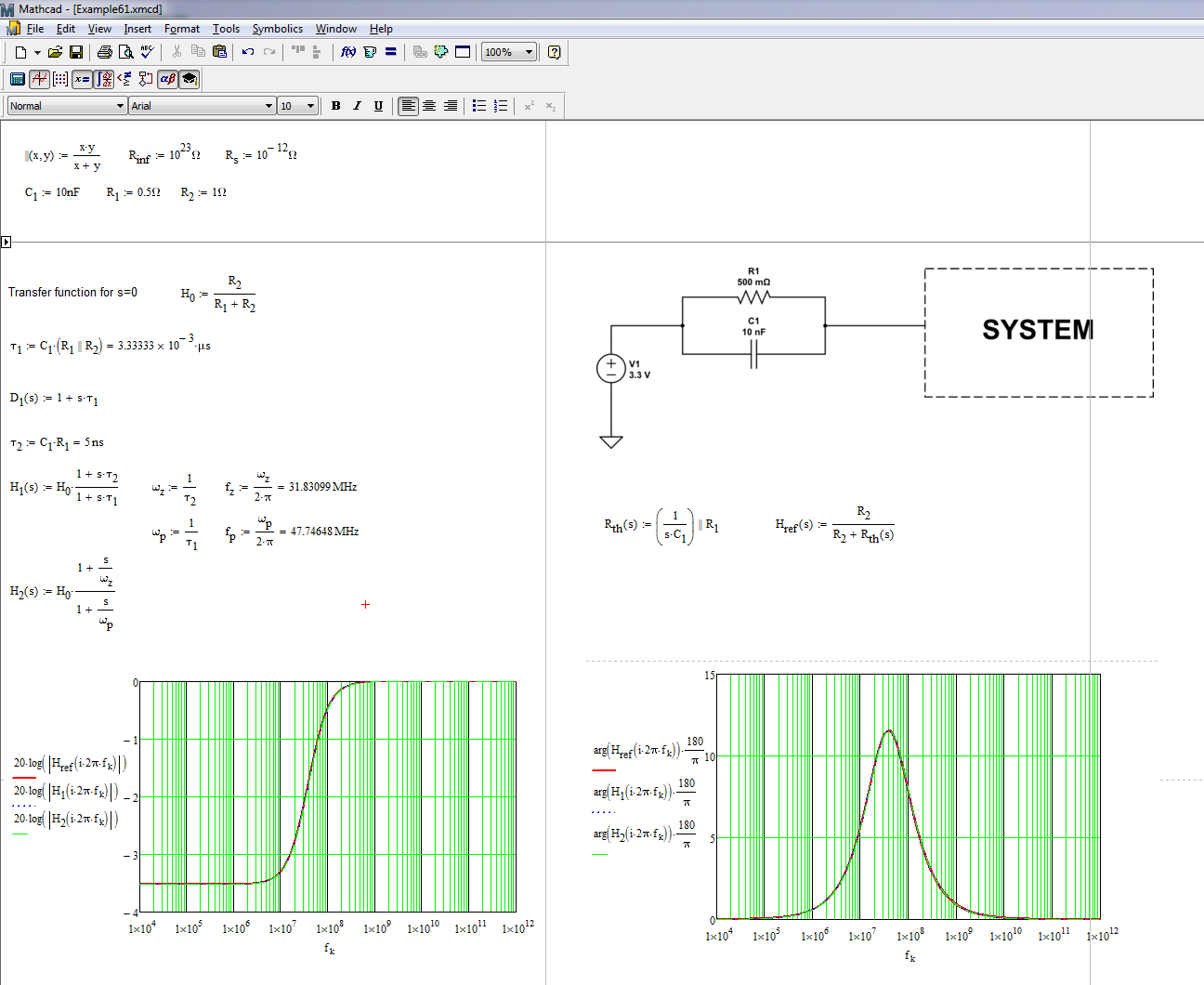
For the zero, it requires a bit of abstraction: what in this circuit could prevent the excitation from reaching the output for a certain value of \$s\$? If the impedance made of \$C_1\$ and \$R_1\$ in parallel approaches infinity at the zero frequency, then there is no response. We can write \$Z_1(s)=\frac{1}{sC_1}||R_1=R_1\frac{N(s)}{1+sR_1C_1}\$. This expression features a pole (which makes it go infinite) and it is the zero of our system: \$\omega_z=\frac{1}{R_1C_1}\$. The complete transfer function can thus be expressed as \$H(s)=H_0\frac{1+\frac{1}{\omega_z}}{1+\frac{s}{\omega_p}}\$. The below Mathcad sheet shows the resulting dynamic response:

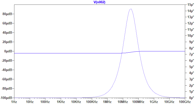
I did not write a line of algebra and in case I made a mistake (for instance if I see a deviation between the derived expression and the raw expression \$H_{ref}\$ in the above picture, then I can easily fix the guilty intermediate step. This extremely useful and unbeatable when dealing with higher-order circuits.


