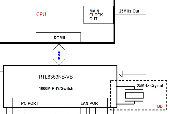
I got a circuit design problem. There is a ethernet switch in my circuit. It is needed 25Mhz crystal input.
There are two option, 1). Using external crystal. 2). Using CPU clock output.
Its block diagram is shown as below.
However, I wanna co-layout both solution, witch means layout these both two solution on the PCB, but finally only chose one solution in the product. For this example, if I chose clock from CPU, it won't mount external crystal, but if I chose clock from external crystal, the clock from CPU won't affect the input clock to ethernet switch.
My question is how to fulfill this idea in my circuit of crystal side?
Kind regard, Zu Wang.

