0
\$\begingroup\$

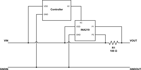
I am tinkering with the problem of making a circuit which uses INA219 for measuring power consumption on high side. The circuit has only one power input and only one power output as pictured below (very simplified only to convey the idea). The power for INA219 and its controller in that schematic is drawn before current sense resistor so to avoid INA219 detecting power drawn by those parts and to only measure power drawn on output end of the circuit.

The problem starts when I am thinking of how to make input/output reversible. With the diagram below it still will work in reverse (that is when VOUT/GNDOUT become input and VIN/GNDOUT are connected to the load). Using circuit below with IN/OUT reversed the INA219 will still function, but now the data it outputs will include power drawn by its controller (and any other peripherals connected to it).

So the question is -- how do I modify this circuit to allow this being reversible, but at the same time avoid INA219 detecting power drawn by controller?
schematic

simulate this circuit – Schematic created using CircuitLab

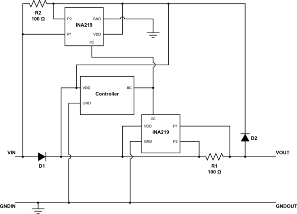
I could in theory insert diode right after VIN, then branch near VOUT and have 2nd current sensing resistor and 2nd INA219 on that branch just like below (diode placement are not exact there, again this is just to convey the idea). But this would mean rather complex circuit and also significantly increases cost of this circuit. Are there any better alternatives to that?
schematic

simulate this circuit

\$\endgroup\$

1 Answer 1

0
\$\begingroup\$

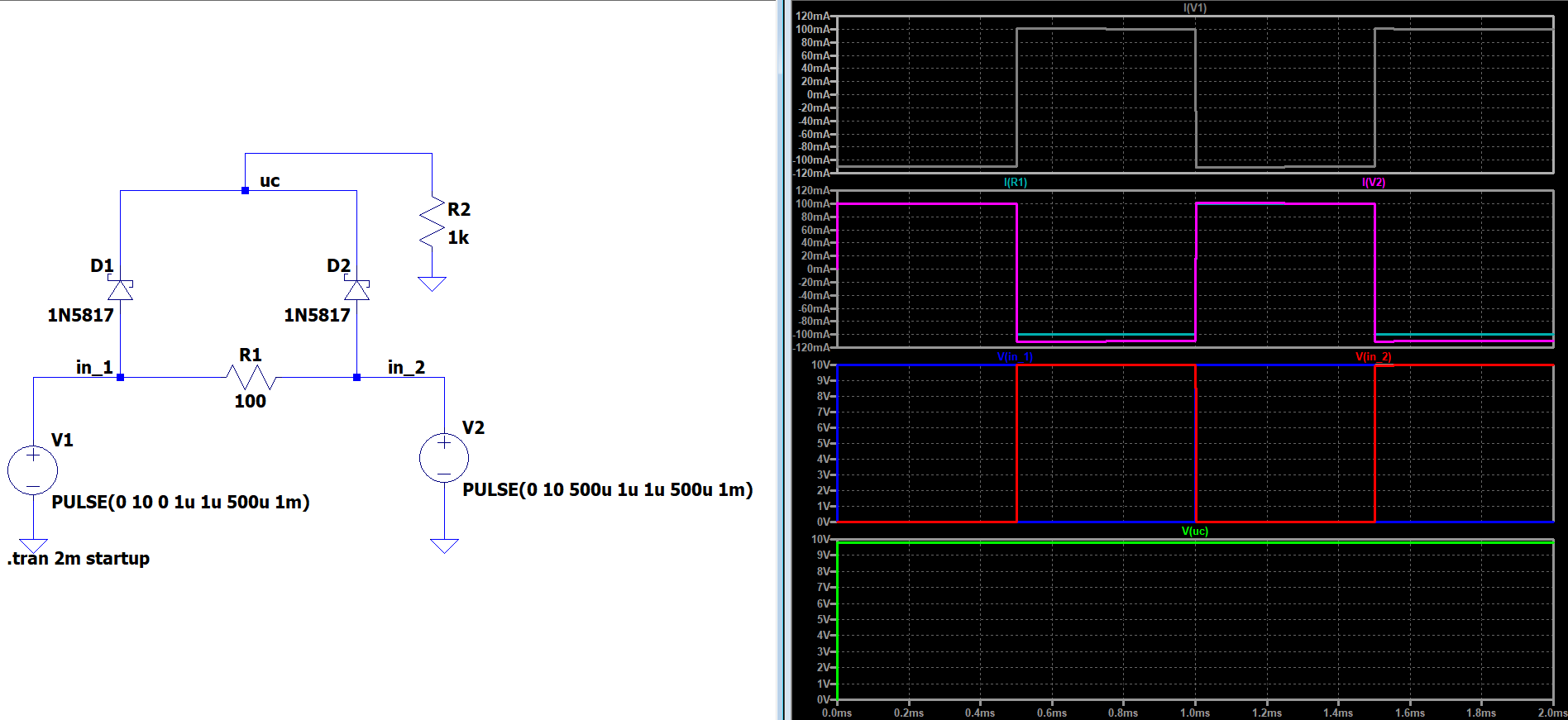
Provided that you have some small current flowing through the sense resistor, you could theoretically add two schottky diodes in parallel to the sense resistor. The diode connected to the higher supply voltage would always take precedence because of the voltage drop caused by the sense resistor.

circuit 1

EDIT #1

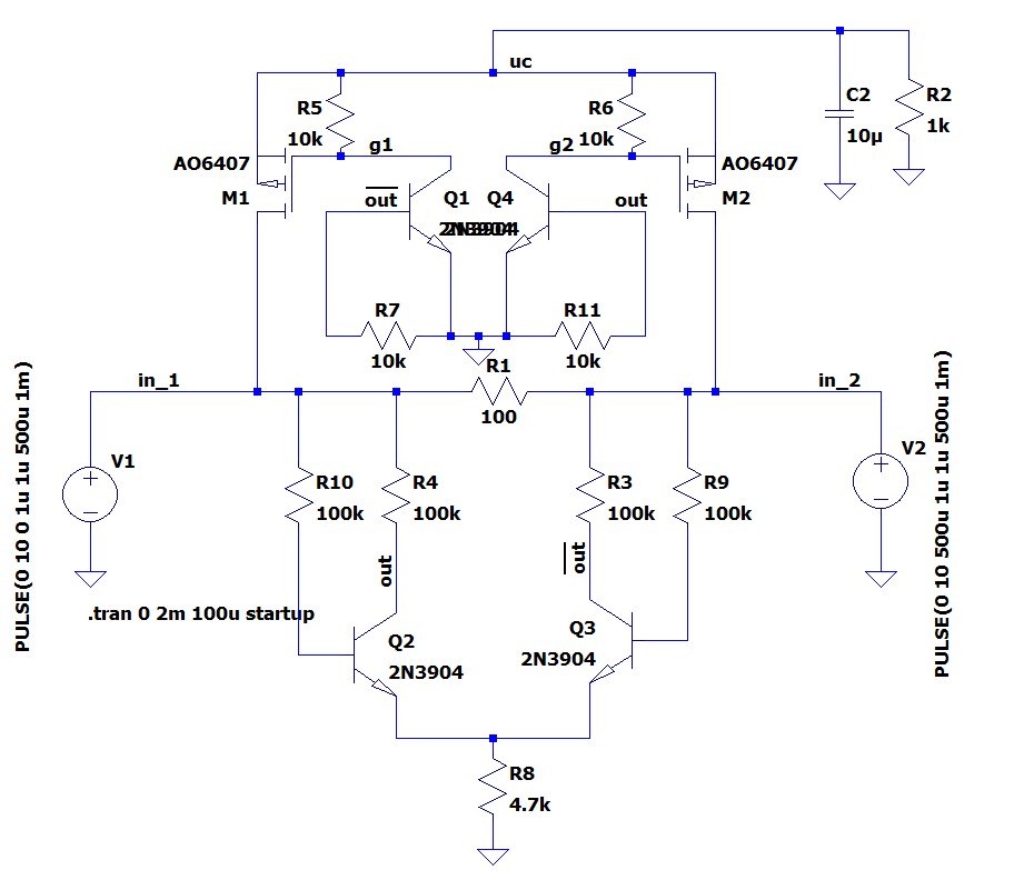
If you want to make things a bit more complicated, and implement some sort of active supply voltage switching, you could try the following or something similar:

How it works:

The lower branch forms a long-tailed pair which measures the voltage across the sense resistor, and based on the polarity of the voltage it turns on the corresponding Bipolar / FET.

e.g. If $$V_1>V_2\rightarrow V_{out}\approx 0V \rightarrow Q_4 and M_2 are OFF$$ AND $$\overline{V_{out}}\approx 600mV \rightarrow Q_1 and M_1 are ON$$

Therefore, current is supplied by \$V_1\$. Ditching a conventional opamp and using discrete elements makes it possible to reduce the current consumed by the differential pair substantially. However, it would also be possible to implement it using opamps.

enter image description here

\$\endgroup\$
2
  • \$\begingroup\$ I think that would still cause some power going through the diode on load side due to diode internal resistance. Which is exactly what I would like to avoid as this is intended for rather precise measurements. \$\endgroup\$ Commented Apr 5, 2020 at 7:25
  • \$\begingroup\$ Since the current flowing through the load side's diode causes a voltage drop equal to \$V_{drop} = I_{load}\cdot R_S + V_{D,fwd}\$, the uC and the sensor will draw current from the supply rail with the higher voltage. I will update my answer, in case you still want some active switching. \$\endgroup\$
    – vtolentino
    Commented Apr 5, 2020 at 7:55

Your Answer

By clicking “Post Your Answer”, you agree to our terms of service and acknowledge you have read our privacy policy.

Not the answer you're looking for? Browse other questions tagged or ask your own question.