2
\$\begingroup\$

I'd like to measure the output voltage on a power supply with a ADC and a micro-controller. The ADC is powered from a different source and the grounds of the power supplies are not connected. How can safely I measure the differential output voltage of the power supply? I'm sorry if this is a standard question, but I can't find a simple solution.

Edit in response to the comments: The voltages I want to measure range between 0 and 14V. Precision is not important (a few percent). Frequency of measurements is low (about 1Hz). No high frequency components present.

\$\endgroup\$
10
  • \$\begingroup\$ What's the range of voltage that you are trying to measure? (From what value to what other value?) Would you be willing to consider anything other than using your ADC to make these measurements? How often will you be making the measurements? What precision is needed? \$\endgroup\$
    – jonk
    Commented Nov 11, 2017 at 18:53
  • \$\begingroup\$ Also, are you expecting there to be any higher frequency (>100HZ) components to the voltage that you're measuring? \$\endgroup\$
    – BeB00
    Commented Nov 11, 2017 at 18:57
  • \$\begingroup\$ The voltages I want to measure range between 0 and 14V. Precision is not important (a few percent). Frequency of measurements about 1Hz. No high frequency components present. \$\endgroup\$
    – hanno
    Commented Nov 11, 2017 at 19:05
  • \$\begingroup\$ you did not say that grounds had to be separate. ... use a battery to power the ADC and the μC, connect the ground between the PS and μC. use opto-couplers on any outputs from μC to outside world. \$\endgroup\$
    – jsotola
    Commented Nov 11, 2017 at 19:23
  • 2
    \$\begingroup\$ you can get a cheap DMM with serial out (ex: ut61e), then a serial to uart adapter. \$\endgroup\$
    – dandavis
    Commented Nov 12, 2017 at 6:58

2 Answers 2

3
\$\begingroup\$

If your grounds are guaranteed to be close, and the voltages are within the common mode range, a simple differential amplifier may be enough.

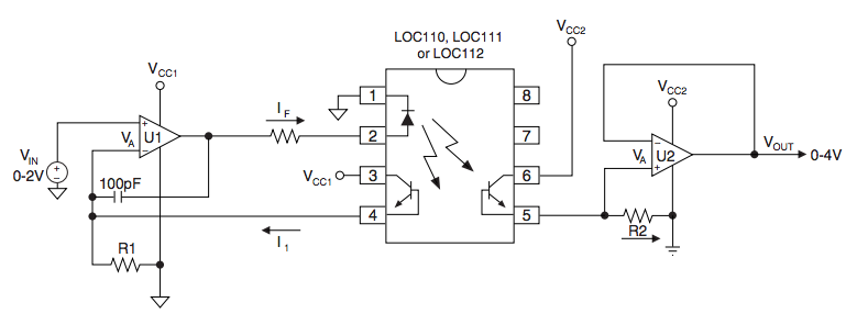
Otherwise, depending on the accuracy you need, your best bet is probably to use a linear opto-coupler circuit.

enter image description here

In your case the left side would be powered from the thing you are testing and the Vin would be some division of that voltage. However if the source goes below the supply requirements of U1, that will not work.

\$\endgroup\$
2
\$\begingroup\$

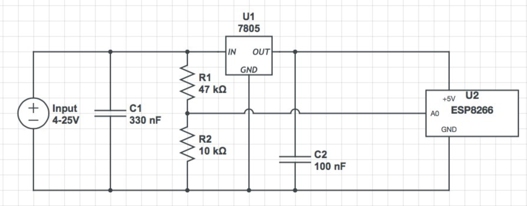
I came up with the most hackish solution possible: Using an ESP8266 to stream the data wirelessly. It works.

enter image description here

\$\endgroup\$

Your Answer

By clicking “Post Your Answer”, you agree to our terms of service and acknowledge you have read our privacy policy.

Not the answer you're looking for? Browse other questions tagged or ask your own question.