2
\$\begingroup\$

I am still trying to figure out the very basics of electronics, or certainly the parts I need to know for what I am trying to do.

I've got the very basics (when it comes to using LEDs). + is Positive - is Negative. Resistors are required in order to pump 12v through 3.3v LEDs without burning them out. I can chain 3 LEDs in series per single resistor.

This is where I get confused, and I am not sure if it is just the online simulator I am using that is confusing me.

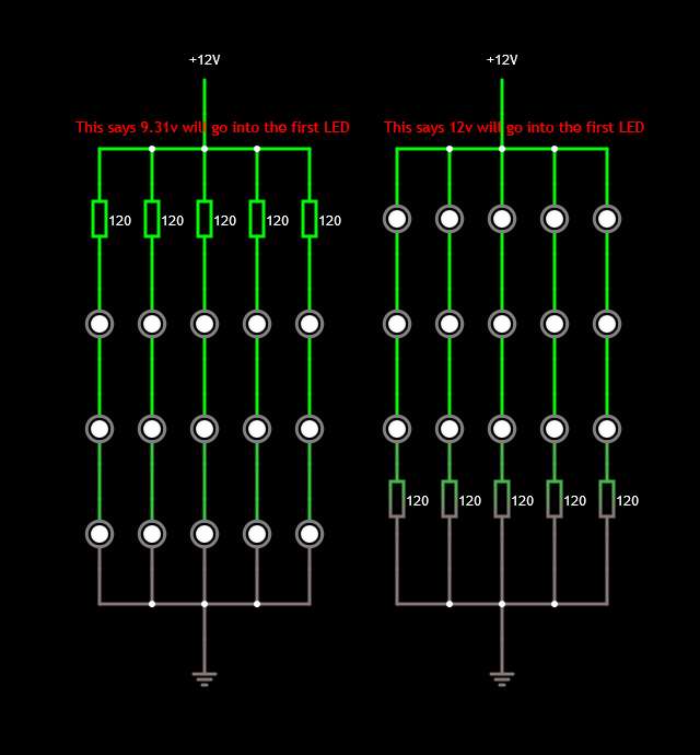
So, for example, take 5 chains of 3 LEDs (3.3v) with a 120ohms resistor (as suggested by the LED series/parallel array wizard.

So, my question(s).

Should the resistor be placed before or after the LED? Or more specifically, the 12v side or the ground side?

In the image below, you can see I've tried both. The left one (resistor placed before - Suggested by LED series/parallel array wizard) still says 9.31v is flowing into the first LED, and the right one (resistor placed after the chain) says 12v is flowing into the first LED.

Wouldn't both burn out the LEDs as they are only meant to have 3.3v? Or am I massively misunderstanding all this?

enter image description here

Thanks in advance.

Edit: I was told to edit my post to explain how my question differs from another. The reason for that is I know very little at this point, and I didn't understand a word of the other question. It helps me to understand by wording it in a way I understand. I can then translate my own understanding based on the answers I receive. Thanks

\$\endgroup\$
1
  • 1
    \$\begingroup\$ Thanks. I did notice that post, however that person has a greater understanding than I do currently, as I didn't understand a word of it. Sorry. \$\endgroup\$ Commented Nov 18, 2017 at 10:05

4 Answers 4

6
\$\begingroup\$

For the led chains it makes no difference. The total voltage over the led chains remains the same in both arangements.

The only difference is the potential difference in respect to earth,

Instead of looking at the potential ( voltage going into the led) you should look at the voltage across the led.

\$\endgroup\$
1
  • \$\begingroup\$ Right got you. According to what I can tell they are the same in both cases. They show as follows: I = 22.4mA - Vd= 3.1V - P = 69.56mW - Vf = 3.3V - P = 69.56mW \$\endgroup\$ Commented Nov 18, 2017 at 9:59
11
\$\begingroup\$

As others have mentioned it does not matter where you put the LED in the series chain. You can even put them in the middle if you want.

However, there is another factor not discussed here so far.

If the LEDs are remote from the source, you really do not want to pass the raw power rail through the wire that goes to the LEDs. The reason being, if there is a short to ground out there somewhere you are shorting your entire power supply. As such, it is normal practice to put the resistor on the high side to provide a little protection.

\$\endgroup\$
6
\$\begingroup\$

Both are equivalent.

Writing that 9.31V or 12V will go into the first LED makes no sense. In reality, there is no such thing as a voltage in one point. Only voltage differences between two points exist. The ground at 0V is only a convention. Each LED will only see 3.1V between its pins.

\$\endgroup\$
6
  • \$\begingroup\$ Thanks. It probably doesn't make any sense because I am still trying to understand it. "Each LED will only see 3.1V between its pins": Is that what is referred to as "Voltage Drop" ? \$\endgroup\$ Commented Nov 18, 2017 at 10:03
  • 1
    \$\begingroup\$ Don’t worry too much about that, that’s a very common misunderstanding. Yes, that is voltage drop. \$\endgroup\$ Commented Nov 18, 2017 at 10:08
  • \$\begingroup\$ Great, at least that is 1 term I understand now, thanks. Similar to the above example, (to simplify my wiring), if were to use two LEDs in a chain, could I place the resistor (330ohms) between them for the same result? \$\endgroup\$ Commented Nov 18, 2017 at 10:13
  • 1
    \$\begingroup\$ @DominicJamesSibthorp. Placing the resistor in between leads to the same result. But again the potentials at the various point in respect to 0 will change. \$\endgroup\$
    – Decapod
    Commented Nov 18, 2017 at 10:18
  • 2
    \$\begingroup\$ It's current that flows, just like water down a stream. Voltage is more like the difference in height that causes the water to flow. \$\endgroup\$
    – Finbarr
    Commented Nov 18, 2017 at 11:52
3
\$\begingroup\$

This is a common misconception that every beginner including me had once. In a circuit with an LED and a series resistor, the only thing you have to worry about is the voltage applied across them, and whether the total current flowing through them, exceeds the current rating of the LED. Say if the applied voltage Vin > LED's forward Voltage (3V), then current starts flowing and a voltage, V = (Vin - 3 ) volts drop across the resistor and a current = V/R flows. If you still want to think " what goes into LED first ? ". Just check how is the current flowing. No need to think like "voltage goes into LED first "

\$\endgroup\$

Not the answer you're looking for? Browse other questions tagged or ask your own question.