3
\$\begingroup\$

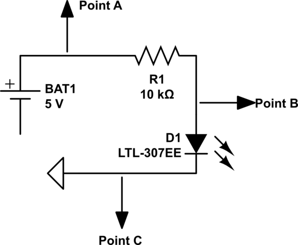
I am an electronics beginner and I created a small little circuit, just a battery a resistor and a led, then to ground. This is the circuit:

schematic

simulate this circuit – Schematic created using CircuitLab

Now I have a few questions about it. I know voltage is the different of electrical charge between two points, so I measured that difference:

Point A to B: 3.27V Point B to C: 1.82V

  1. First question: Does that mean that the actual voltage of: Point A: 5V Point B: 1.73V Point C: 0V?

So I am not sure if my calculations of voltage are correct. I also have this other questions:

  1. Does the resistor have to be before the component I am trying to protect, like an LED. I have seen people place it after, but wouldn't that give a full 5V to the led or component?

  2. Ground has a neutral charge right? so why do electrons want to travel so badly to a point that has no electric charge?

Thank you

\$\endgroup\$
5
  • 1
    \$\begingroup\$ "the actual voltage". Voltages aren't absolute, they are the difference in potential between two points. If by "actual" you mean, "referenced to point C", then yes. \$\endgroup\$ Commented Aug 23, 2016 at 2:18
  • 3
    \$\begingroup\$ Your diagram doesn't show a circuit. Having read the answers, do you understand why? What do you need to add? \$\endgroup\$
    – Neil_UK
    Commented Aug 23, 2016 at 5:14
  • \$\begingroup\$ No. ...................................... \$\endgroup\$
    – Russell McMahon
    Commented Aug 23, 2016 at 15:40
  • \$\begingroup\$ @Neil_UK is it become the circuit doesn't have anything connected to the negative end of the battery? can't ground replace that? \$\endgroup\$
    – ptt
    Commented Aug 23, 2016 at 20:31
  • 2
    \$\begingroup\$ @Pablo Yes, and yes. So if you want to show a circuit, edit your schematic to put a ground symbol on the -ve end of the battery. Even if you have actually made a circuit, you haven't drawn what you have made, you've drawn something else. This will confuse your readers. \$\endgroup\$
    – Neil_UK
    Commented Aug 24, 2016 at 5:15

4 Answers 4

5
\$\begingroup\$

The resistor and LED are in series. It doesn't matter for the purpose of lighting the LED what order they are in.

You are confusing voltage and charge. What you are looking at are voltages. That's not the same thing as charges.

Voltages are relative to each other, like your A --> B, B --> C, etc. Ground is a name we give to that one node in a circuit that we implicitly consider to be at 0 volts. Then we can pretend other voltages are absolute, although they are really relative to this ground node.

In radio and some power applications, ground can also mean true earth ground. However, that doesn't apply to your circuit.

\$\endgroup\$
12
  • \$\begingroup\$ I understood that electrons were attracted to ground, why does that happen if ground has no voltage, it is neutral right? \$\endgroup\$
    – ptt
    Commented Aug 23, 2016 at 12:38
  • \$\begingroup\$ @Pablo: Electrons are not "attracted" to ground. Again, stop thinking about charges. Think of voltage and current instead. You have several bad assumptions that you need to unlearn. \$\endgroup\$ Commented Aug 23, 2016 at 12:47
  • \$\begingroup\$ Ok so electrons are not attracted to ground, so why do people use ground instead of the negative terminal of a battery? what is the difference? \$\endgroup\$
    – ptt
    Commented Aug 23, 2016 at 20:28
  • 1
    \$\begingroup\$ Circuit "Ground" is often, BUT NOT ALLWAYS the negative terminal of the battery. When I designed circuits using ECL logic, "Ground" was the positive terminal of the supply. In many analog circuits, "Ground" is the mid-point of the supplies - you may have +12 Volt and -12 Volt power supplies. \$\endgroup\$ Commented Aug 23, 2016 at 22:14
  • 2
    \$\begingroup\$ In about 99.9% of electronics, "Ground" is just a label we stick on a point in a circuit to indicate that we will consider that point as "Zero Volts". It is where we place the black meter lead when measuring voltages elsewhere in the circuit. There is nothing magic about this Ground, and it has no special powers. \$\endgroup\$ Commented Aug 25, 2016 at 5:03
5
\$\begingroup\$

I understand where you are coming from. You may imagine that if a point is at \$5V\$, then it really is at \$5V\$ in some absolute sense. But the reality is that it is all relative. The \$5V\$ at that point in the circuit might be \$150V\$ when compared to some concrete bolt, somewhere. Or \$10kV\$ relative to some spot high in the air above your head. There is no such thing as an absolute voltage value. You can't measure the voltage on some wire or other conductor. Everything is relative, here.

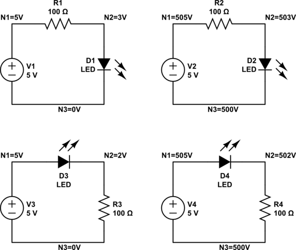
So, let's look at "LED cooked four ways:"
schematic

simulate this circuit – Schematic created using CircuitLab

In the above circuit, I assume that the LED requires \$3V\$ when operating with \$20mA\$ and that resistor \$R_1\$ is designed to limit the current by the formula, \$R = \frac{V_1 - V_{led}}{I_{led}=20mA} = \frac{5V - 3V}{20mA} = 100\Omega\$.

Note that no matter how you look at it, the two nodes on either side of the LED itself are exactly \$3V\$ apart. The two left side panels show \$N_3\$ as \$0V\$, as is often done by convention. In any circuit, you get to set exactly one node (or wiring point) to any value you like. (The rest you don't get to do that with.) Most folks call it \$0V\$ to help simplify things a bit, mentally. (Sometimes, it does mean more than that. But that's a different discussion.) Or just ground. However, as you can see in the right side panels, I've decided to call that wire (node) \$500V\$ instead. It doesn't matter what number I assign it. I could make it a million volts or minus a million volts. The point is that it doesn't really matter, so long as all you are focused on is the circuit itself.

It will matter, though, if a circuit is connected in some way to other circuits. But for any local schematic where you are ignoring the rest of the universe while looking at it, then it's all relative.

Circuits can float. So, for example, if you are in the middle of lightening storm and you are holding your cell phone in your hand, it's quite possible that the nearby local earth ground is sitting at \$-10kV\$ and the air high above you is sitting at \$+40MV\$, and you and your cell phone are actually somewhere in between that, at say \$+10kV\$. Chances are, all of the circuit elements in your cell phone are also elevated to around \$+10kV\$. But since all the wires are relative to each other the circuit still works okay and as it was designed to work. (Just so long as the lightening doesn't strike you to release all that tension in the air!)
\$\endgroup\$
1
\$\begingroup\$

Since your drawing does not show a complete circuit (the negative terminal of the battery is not connected to anything), no current can flow, so there can be no voltage drops across any component.

In most circuits, "Ground" is just the point that we choose to call "Zero Volts", and use as a reference when measuring voltages elsewhere in the circuit. It has no special "magical" properties - it is just a label we place for our convenience. These days, "Ground" is usually chosen as the most negative point in the circuit, but it could instead be the most positive. For many audio and linear circuits, Ground is the mid-point of the power supplies, and we have both negative and positive voltages in the circuit.

So, with no current flowing, thus no voltage drops, all points in your drawing are at Zero volts, except the negative terminal of the battery, which is at -5 volts.

If you intended the negative terminal of the battery to be connected to Ground, then your voltage reading would make sense.

By Kirchoff's current law, the current is the same at all points in a simple series circuit, as you attempted to draw, so it makes no difference what order the components are connected.

\$\endgroup\$
3
  • \$\begingroup\$ I measured the voltage of the points with a multimeter and got positive values, for instance of 5v. Isn't ground a replacement of the terminal end of a battery? what is the difference between ground and the negative end of a battery? why do people use ground? \$\endgroup\$
    – ptt
    Commented Aug 23, 2016 at 20:30
  • 1
    \$\begingroup\$ As I said in my second paragraph, "Ground" in most circuits is just the point that we want to call "Zero Volts". The negative terminal of the battery is often connected to this "Zero Volt" point, but we should not assume that it is. In your original circuit, you did not show the negative terminal of the battery connected to anything, so I have to assume that it is indeed not connected to anything. If you connected a ground symbol to the negative terminal, then I would assume that it was connected to the other ground symbol, but as is, the circuit is incomplete. \$\endgroup\$ Commented Aug 23, 2016 at 22:05
  • \$\begingroup\$ I would prefer to call the "Zero Volts" point of a circuit "Common" or "Reference", but the misuse of "Ground" for this point is so widely established that I expect that generations to come will continue to be confused by it. \$\endgroup\$ Commented Aug 23, 2016 at 22:07
1
\$\begingroup\$
  1. In Electrical circuit, whatever you measure, you measure wrt some reference i.e. Ground. so if point A is 5V it means it's potential WRT to GND is 5V. if B is at 1.73V it means it's its potential WRT GND. so every potential you measure at any point is relative i.e. wrt GND. Those are not your absolute potential. if you try to observe potential of point A wrt to Point B it'll show you 3.27V which in nothing but PD between points A & B.

  2. total Current flowing thorough the circuit depends on the equivalent resistance of the circuit. It doesn't matter in what order components are arranged as long as the total resistance of the circuit doesn't change current will not change. In your circuit 10K resistor is use to limit the current. it doesn't matter whether you put it before or after the LED, because equivalent resistance will be the same hence the current.

  3. Suppose a situation where in a U shaped tube has equal water level in it's both the sides. will there be any flow of water? No. right! similarly if two points are at equal potential no current flows. But if there's a difference in their water level, water will flow from higher level to lower level. Similarly in your circuit point A is at higher potential & point C is at lower Potential (which is GND) & that's the reason electron moves towards GND.(technically Conventional Current is opposite to that of actual flow of electrons but the concept remains the same)

\$\endgroup\$
2
  • \$\begingroup\$ I am sorry for my ignorance, I tried to look it up but I couldn't find a decent definition, what is WRT? \$\endgroup\$
    – ptt
    Commented Aug 23, 2016 at 20:30
  • 1
    \$\begingroup\$ WRT = "With respect to". People shouldn't use TLAs (three-letter acronyms) without defining them. \$\endgroup\$ Commented Aug 23, 2016 at 22:09

Not the answer you're looking for? Browse other questions tagged or ask your own question.