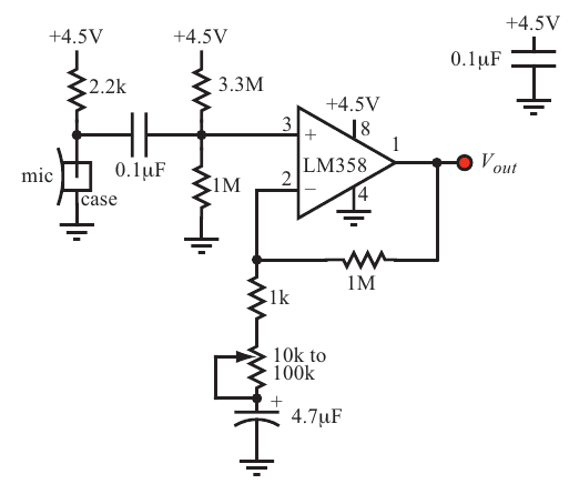
I will be using the attached circuit diagram to build a Phono Cardio Gram (output of the attached circuit through a band pass filter and the microphone attached to a stethoscope). I need help understanding the functions of the various resistors and capacitors in the circuit. From reading this https://thephysicsportal.wordpress.com/2012/02/22/day-8-more-op-amp-circuits/
I believe that the opamp is used as a non inverting, integrating amplifier? I understand that the 1 M resistor is for nullifying the drifting D.C offset but is clueless about the resistors in series with the capacitor and the other capacitor -resistors combination at the non inverting input. Any help would be much appreciated. AJ
AJ
2 Answers
The arrangement of the 1M, 1k, variable resistor and 4.7 uF cap is a feedback circuit which determines the gain of the amplifier.
If we ignore the 4.7 uF capacitor for a moment and pretend that it is a short, the gain of the opamp + feedback is roughly equal to the ratio of the 1 M resistor divided by the sum of the other resistors. So here the gain will be between 1000 (variable resistor at smallest value) and 10 (100 k ohm variable resistor at largest value).
Now the 4.7 uF capacitor: its function is to block DC current so the resistance of the 1k ohm + variable resistor + 4.7 uF cap. will be infinite for DC. That means these 3 components are basically "not there" for DC.
So for DC only the 1 M feedback resistor is present and then the opamp is in a unity gain configuration meaning the gain is 1 (one) so no amplification at DC. This is useful as we're only interested only audio signals which are AC.
If at DC the opamp's gain is 1x, what then sets the DC voltage at input (and output since the DC gain is 1)? It is set by the 3.3M and 1M resistors at the input, they bias the input at about 1 Volt DC.
By not amplifying DC any DC offsets at the input of the opamp do not matter much. It makes the design easier and more robust.
To learn more about opamp based circuits read: Opamps for everyone which is a free Ebook from Texas Instruments.
-
\$\begingroup\$ Thank you very much. I will read up more on op-amps. \$\endgroup\$ Commented Nov 19, 2017 at 21:28
-
\$\begingroup\$ A clear answer (+1) but I think you forgot to mention the function of the 3M3/1M0 as a DC offset to allow the AC swing at the output. \$\endgroup\$ Commented Nov 20, 2017 at 11:34
-
\$\begingroup\$ @JImDearden True, I did not mention the DC biasing point at the opamp's input, let me add it. \$\endgroup\$ Commented Nov 20, 2017 at 11:36
-
\$\begingroup\$ Would the bandwidth go down to 1kHz at a gain of 1000 with a gain bandwidth of 1MHz? If I understand gain bandwidth properly and have read the datasheet correctly! \$\endgroup\$– DiBoscoCommented Nov 20, 2017 at 11:46
-
\$\begingroup\$ @DiBosco Yes, the Gain Bandwidth product remains constant so at gain = 1000 you can indeed expect a BW of 1 kHz. If you really need 1000x gain then it is much better (more predictable) to use two stages with a gain of 32. (32 x 32 is around 1000). \$\endgroup\$ Commented Nov 20, 2017 at 12:28
Following up on Bimpelrekkie, the DC gain of the circuit is ONE, thus Vout should be within a few milliVlts of the voltage defined by 3.3M and 1M voltage divider. Use a DVM and measure across the OpAmp, from Vin+ to Vout. If thet voltage is not very close to zero +- 10milliVolts (e.d. if is 1 volt), then something is wrong, such as the OpAmp cannot perform accurately that close to Vout = zero, and try a larger VDD or use 3.3Meg in both locations, etc.
