0
\$\begingroup\$

I have to say first of all that I'm not an electronics expert, but I have some basic knowledge.

I want to connect the ADS1115 circuit to my uC using I2C, and measure the "battery level". My problem comes with the powering: ADS1115 is powered by the uC and because of that when the uC turns off it does too, but obviously the battery I'm trying to measure doesn't and keeps applying energy to ADS1115 which is of course not desireable and could burn it.

Of course I can use a relay and cut the connection between ADS and battery but I'm wondering if can make up something using 2N2222 transistor that I already have.

I'm thinking on something like the foloowing but I'm almost sure that it will not work.
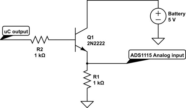
schematic

simulate this circuit – Schematic created using CircuitLab

Reading through my own post I have to say that is really confused, let try to explain my porpouse better and adding some extra info that could help. I have some circuits in charge of stabilize the battery power, output of this circuit is connnected to the uC and ADC is sharing this output (that is what I mean when I said power by the uC and not using a PWM, GPIO or another uC output, I know not clearily explained). I think that this part is clear now, lets continue with my problem, when power supply is off, the previously mentioned output is not suppling energy, but the ADC is still connected to the battery and this cause the ADC to get hot and may end burned, because of that I need a way to cut the connection between ADC and battery when power supply is off, I was trying to avoid using relays and use 2n2222 because I already have a bunch of it and I was thinking on something like the picture above, I know it won't work but hopefully some modifications over it could get it working.

Any ideas? What can/should I do?

\$\endgroup\$
5
  • 1
    \$\begingroup\$ In the circuit you've shown, the ADS1115 will always try to measure a voltage level of \$V_{uC-out} - V_{BE}\$ (probably 4.3 ~ 4.4VDC), not the actual battery level. I would recommend a practical circuit but you need a small signal PNP transistor (2N2222 is NPN btw). \$\endgroup\$ Commented Nov 24, 2017 at 11:08
  • 1
    \$\begingroup\$ To be clear, what exactly do you mean when you say the ADC is powered by the micro? Do you use a GPIO pin to power it, or do you set the ADC into single shot mode via the I2C interface? \$\endgroup\$
    – awjlogan
    Commented Nov 24, 2017 at 20:03
  • 1
    \$\begingroup\$ YOu would really need to add a lot more of the schematic than that. Not much of this question makes any sense, and the little schematic you did give us does not help matters. \$\endgroup\$
    – Trevor_G
    Commented Nov 24, 2017 at 21:16
  • \$\begingroup\$ To repeat others: (a) Please supply a detailed & accurate schematic of your design, with component part numbers. (b) Your question is confusing. Your text suggests you want to control the power supply to the ADS1115, but your schematic "snippet" shows you trying to control a signal to the ADS1115. Please edit your question to clarify. (c) You said: "ADS1115 is powered by the uC" That is ambiguous, but interpreted literally it is rarely true; ensure your schematic shows all power connections. I suspect your answer will be simple, but interpretation is difficult due to lack of clarity. \$\endgroup\$
    – SamGibson
    Commented Nov 24, 2017 at 23:02
  • \$\begingroup\$ Edited trying to explain my situation better :) \$\endgroup\$
    – RobertAA
    Commented Nov 28, 2017 at 7:41

1 Answer 1

1
\$\begingroup\$

I asked which micro controller you are using but a mod decided (without notification) to delete the question, sad as it is entirely relevant to your question. Many micro controllers have A/D so using an I2C device would not be needed, hence lowering the cost of the cct.

From the data sheet The ADS111x operate in either continuous-conversion mode or single-shot mode. The devices are automatically powered down after one conversion in single-shot mode; therefore, power consumption is significantly reduced during idle periods Leaving it connected is not a problem as it was designed to be left connected. Power it off the battery as during shut down current is minimal.

\$\endgroup\$
3
  • 3
    \$\begingroup\$ I'm sure the moderator deleted it because it was a comment.. not an answer. \$\endgroup\$
    – Trevor_G
    Commented Nov 24, 2017 at 21:15
  • \$\begingroup\$ It was a question although maybe I should have added it to comments. \$\endgroup\$
    – LateDev
    Commented Nov 24, 2017 at 21:33
  • 1
    \$\begingroup\$ You seem to be new here, so welcome to EE.SE! You said: "maybe I should have added it to comments" At the moment, you can't add comments - and please don't use the space reserved for answers, for anything else. This topic on the Meta site explains why there is that limitation on the Stack Exchange sites, and how to get the reputation points needed to earn the "commenting privilege". It seems you haven't viewed the site tour - I recommend that you do that, to get familiar with the site ethos. Welcome! \$\endgroup\$
    – SamGibson
    Commented Nov 24, 2017 at 23:15

Your Answer

By clicking “Post Your Answer”, you agree to our terms of service and acknowledge you have read our privacy policy.

Not the answer you're looking for? Browse other questions tagged or ask your own question.