3
\$\begingroup\$

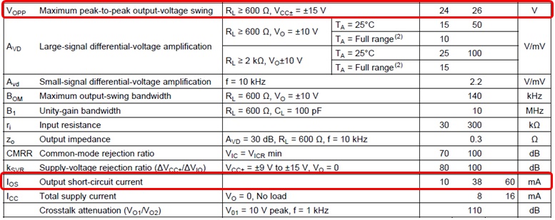
In experimenting with a follower circuit using an NE5532 opamp, I am trying to determine the maximum allowable output current for design purposes. The datasheet is lacking curves in this area, but here is an excerpt from the specs.

enter image description here

From another post here which I can't seem to find, it was explained that Vopp is the guaranteed voltage attainable for the given load, which comes to 20mA amplitude (12V/600Ohm). However, below, the minimum short circuit current is given as 10mA.

So should I assume that some NE5532s can only output 10mA, and design around that? Or is the Vopp calc better? And what if I'm running the opamp from a single supply 12V instead of +/-15V, can I assume that it's the same?

\$\endgroup\$
9
  • 3
    \$\begingroup\$ They provide a schematic with a \$15\:\Omega\$ resistor near the output. See it? Roughly speaking, this means about \$\frac{600\: \textrm{mV}}{15\: \Omega}=40\:\textrm{mA}\$ is the output limit. The line you selected confirms this rough estimate, but includes part, temp, and operating voltage ranges. Looking at the \$A_{VD}\$ line, I would say they are recommending \$R_L\ge 2\:\textrm{k}\Omega\$ at \$10\:\textrm{V}\$ operation, or about \$5\:\textrm{mA}\$ max at the output. I'd probably stay under that figure. They allow for more on a different line, of course. But that's my read of things. \$\endgroup\$
    – jonk
    Commented Nov 24, 2017 at 20:25
  • 2
    \$\begingroup\$ And remember that at short circuit the output voltage is zero so the op-amp is useless in that condition. \$\endgroup\$
    – Transistor
    Commented Nov 24, 2017 at 20:31
  • \$\begingroup\$ 12V vs 15 will probably reduce it slightly. \$\endgroup\$
    – Trevor_G
    Commented Nov 24, 2017 at 20:41
  • \$\begingroup\$ Also do not forget it might get a tad warm at higher currents at 85-97C per watt.. \$\endgroup\$
    – Trevor_G
    Commented Nov 24, 2017 at 20:46
  • \$\begingroup\$ @jonk: ouch, I was designing around 14mA absolute max, thinking 20mA was guaranteed. Is my interpretation of the Ios min = 10mA correct, that some amps can only output 10mA max in normal operation? Or is this not relevant if the amp is properly loaded? \$\endgroup\$
    – User7251
    Commented Nov 24, 2017 at 21:33

2 Answers 2

1
\$\begingroup\$

Beware of the increased distortion, once you get within 0.3 or 0.4 volt of turning on the short-circuit current limiter.

The effect of tiny amounts of current limiting (say 0.1% limiting) is the same as instantaneously reducing the open-loop-gain near the peak of the output voltage. You get a small amount of signal-dependent distortion.

\$\endgroup\$
0
\$\begingroup\$

After contacting TI, here are excerpts from the response I received.

"20mA is supported at room temperature (25C) as you said 12V/600 ohms. 25mA assumption is fair, It is reasonable to expect at least this much current from -40C to 85C Nevertheless, the data sheet doesn't directly support this claim.

It is odd that Vopp supports 20mA with a 3V headroom yet a short has a minimum of 10mA. So I checked old data sheet revisions and saw that the 10/60 limits were added in May of 2000. But why was that? I checked for NE5532 competitors at Digikey and saw that other device also has 10/60 limit. So someone replicated the limit and someone else created the original unwarranted 10mA minimum. In any case, 10mA just doesn't make sense.

The Avd spec doesn't show any weakness, but it does indirectly support at least 16.7mA current drive across full temperature range as DC gain is >10k

Here is a 50 amplifier char result for NE5532."

            IOS-        

LotID.Tmp Mean StdDev Mean-3s LowRead HiRead Mean+3s Reads

-----------------+---------------------------------------------------------------------------------

    -40C    |  -48.027mA   105.198uA   -48.342mA   -48.096mA   -47.607mA   -47.711mA       50

    0C      |  -48.044mA    65.629uA   -48.240mA   -48.218mA   -47.974mA   -47.847mA       50

    25C     |  -48.015mA   119.972uA   -48.374mA   -48.096mA   -47.607mA   -47.655mA       50

    70C     |  -46.818mA     1.537mA   -51.429mA   -48.096mA   -41.748mA   -42.207mA       50

    85C     |  -44.633mA     1.124mA   -48.005mA   -45.654mA   -40.283mA   -41.261mA       50

-----------------+---------------------------------------------------------------------------------

        IOS2+    

LotID.Tmp Mean StdDev Mean-3s LowRead HiRead Mean+3s Reads

-----------------+---------------------------------------------------------------------------------

    -40C    |   47.194mA   390.580uA    46.022mA    46.730mA    48.002mA    48.365mA       50

    0C      |   47.032mA   395.059uA    45.846mA    46.094mA    47.525mA    48.217mA       50

    25C     |   46.641mA   310.048uA    45.710mA    46.094mA    47.366mA    47.571mA       50

    70C     |   46.482mA   298.172uA    45.587mA    46.094mA    46.889mA    47.376mA       50

    85C     |   46.434mA   316.390uA    45.484mA    46.094mA    46.889mA    47.383mA       50
\$\endgroup\$
3
  • \$\begingroup\$ Interesting. Thanks for the update. It really did look like there was a conflict in their specifications, once your questions made me look closer at them. But I'm still not sure what you are saying. We know from the datasheet that \$V_{OPP}\$ applies at \$25^\circ\textrm{C}\$. It says at worst \$24\:\textrm{V}\$ of swing into \$600\:\Omega\$, so this means \$20\:\textrm{mA}\$ is guaranteed at \$25^\circ\textrm{C}\$ only. But you conclude: "It is reasonable to expect at least this much current from -40C to 85C" ?? Your conclusion doesn't seem to follow sound logic. Can you elaborate? \$\endgroup\$
    – jonk
    Commented Nov 28, 2017 at 17:28
  • \$\begingroup\$ @jonk: Everything in quotes was copied and pasted directly from the response of the TI rep. I have asked him for elaboration on that point, will post the updated response. \$\endgroup\$
    – User7251
    Commented Nov 28, 2017 at 18:15
  • \$\begingroup\$ Okay. It was his conclusion??? You need to find someone else, I think. I tend to expect a change in \$10^\circ\textrm{C}\$ change to cause a factor of 2 change in current (typical diode behavior.) This also applies to BJTs, as their \$V_{BE}\$ varies with temperature. A well-designed IC will have some additions of course to compensate to a degree. But given the sloppy specifications generally that we are reading on the datasheet, I'd conclude that there are NO specifications at all for \$V_{OPP}\$ at other temperatures. They don't even test it, my bet. Looking forward to hearing what he says. \$\endgroup\$
    – jonk
    Commented Nov 28, 2017 at 18:48

Your Answer

By clicking “Post Your Answer”, you agree to our terms of service and acknowledge you have read our privacy policy.

Not the answer you're looking for? Browse other questions tagged or ask your own question.