0
\$\begingroup\$

I want to trigger an interrupt on an ATMEGA328P, when the current of a load is below a certain value.

Therefore I designed the following differential amp circuit using an LM358

Below picture shows the LTSpice circuit. enter image description here
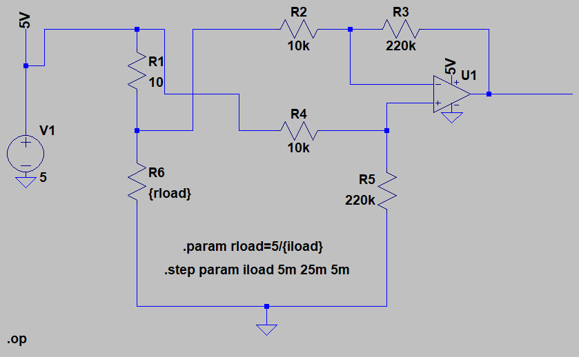
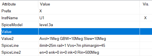
With the following parameters for the LM358. enter image description here
The LTSpice simulation shows the following voltage at the output voltage vs. load current: enter image description here
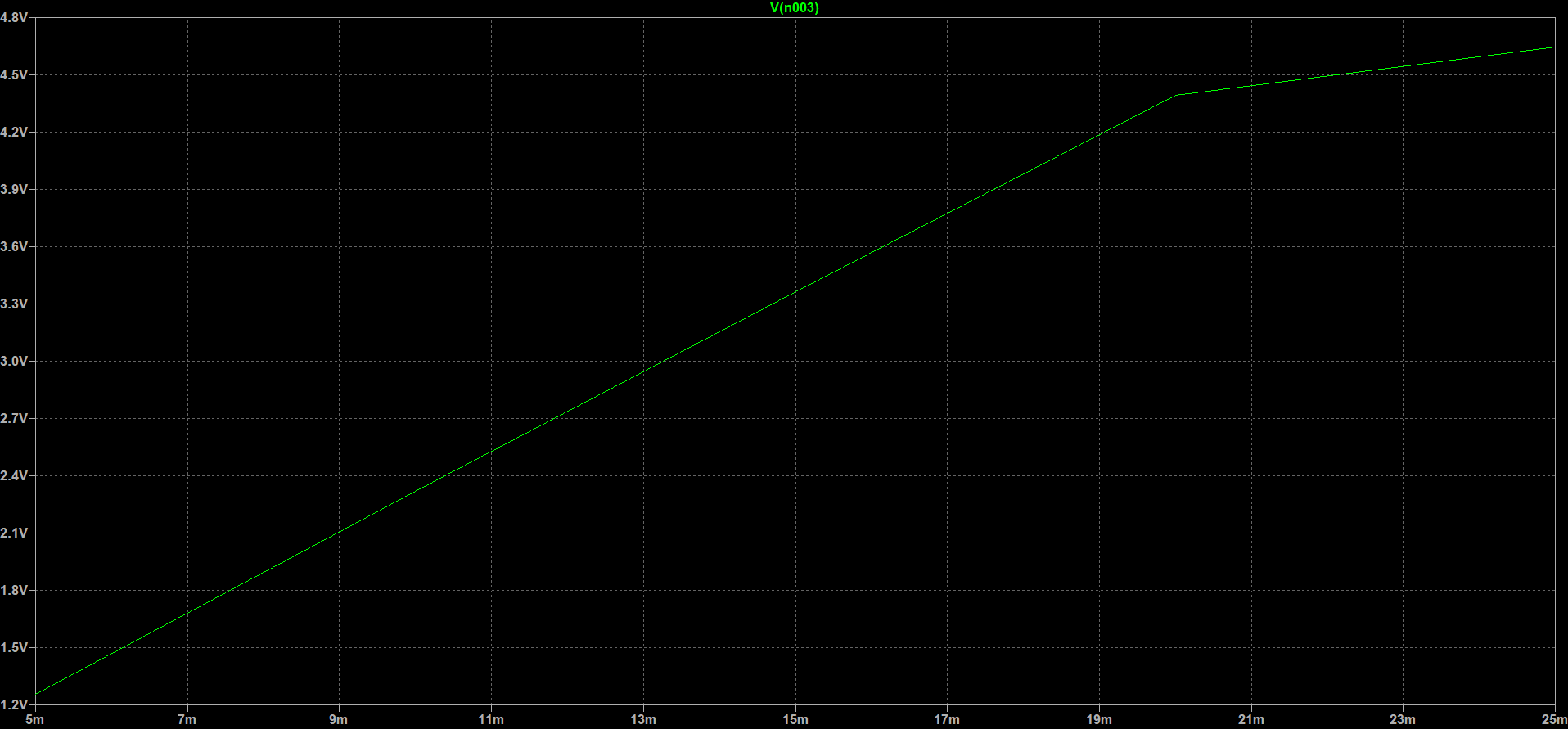
After the simulation, I build this circuit. The potentiometer is used to adjust the gain slightly enter image description here
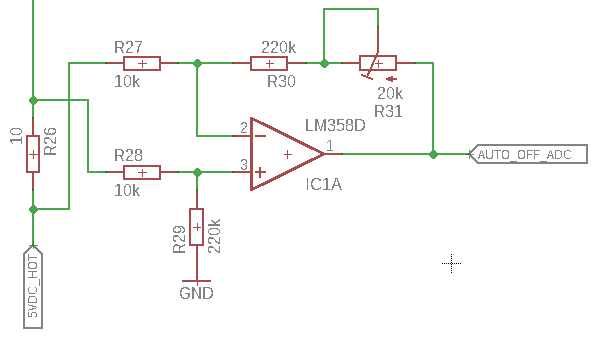
But after building it up, I cannot get it working. From 0 to 100mA Rload the output of the OPAMP remains at 3.8V (5V VCC - VRailOffset). Even with RLoad disconnected the output voltage remains at 3.8V. The voltage measured at the 10Ohm current sense resistor is correct.

The adjustment potentiometer has no effect at all to the output state. I tried different resistor values already (1k/22k and 100k/2Meg).

What am I missing here?

\$\endgroup\$
5
  • \$\begingroup\$ What does "when the current of a magnet falls" mean? \$\endgroup\$
    – Transistor
    Commented May 5, 2018 at 16:19
  • \$\begingroup\$ You switched the inputs: R27 (in the last schematic), in LTspice, goes after the 10\$\Omega\$ resistor, while in the last schematic, it goes before. The reverse is true for R28. \$\endgroup\$ Commented May 5, 2018 at 16:29
  • \$\begingroup\$ @a concerned citizen - I think I didn't. The non-inverting input of the OPAMP goes to the high side in both schematics. or what do you mean? \$\endgroup\$ Commented May 6, 2018 at 11:33
  • \$\begingroup\$ @Transistor: Sorry, was late yesterday :) I changed the wording as it was quit confusing \$\endgroup\$ Commented May 6, 2018 at 11:51
  • \$\begingroup\$ @KarlKarlsom In your top schematic, the 5V rail goes through a 10k resistor in the noninverting input. In your bottom schematic, the 5V rail goes through a 10k res in the inverting input. It's probably confusing since in the upper schem. you have drawn the 5V rail going from up, downwards, while in the bottom schem. is coming from bottom, upwards. \$\endgroup\$ Commented May 6, 2018 at 13:19

3 Answers 3

1
\$\begingroup\$

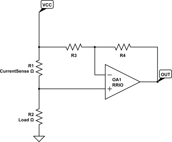
The opamp's input common mode range doesn't reach close enough to the supply voltage to do this. It can reach to 0V but not to VCC.

You could use a rail to rail input opamp, but another problem remains if you want a GND-referenced output: the common mode rejection of the differential amp you built is dependent on resistor accuracy and matching, and thus not very good with 1% resistors.

If you can reference the output to VCC (for example, your ADC uses VCC as its reference) then you can use a rail to rail IO opamp, and you won't have common mode rejection problems.

schematic

simulate this circuit – Schematic created using CircuitLab

If you squint hard enough, this is a non-inverting opamp, with the usual gain of (1+R4/R3), except the input and output are referenced to VCC instead of GND. So,

Vout = Vcc + (1+R4/R3) * (V across R1 with the proper polarity ;)

If the range of your ADC is from 0V to VCC then it'll work just fine, but you do need a RRIO opamp.

If you want a ground-referenced output, then the best is to use a specialized current sense amplifier chip, which already contains everything you need. You can try MAX4376 for example. The reason I'm recommending this one is that it works with input common mode range down to 0V, which is not something that they all current sense amps do...

\$\endgroup\$
1
\$\begingroup\$

An LM358 operated from a 5V supply will not operate properly with inputs at 4.8V.

At 25'C you can get up to about 3.5V, for wide-range operation you should allow more headroom. Increase the op-amp supply (only) to +8V or more and it should work.

As mentioned in the comments, you've changed the circuit between simulation and the 2nd schematic.

If you are planning on trimming the 220K, it would make more sense to use 210K for R30 so the rheostat will be at the mid-point at 220K total.

\$\endgroup\$
1
\$\begingroup\$

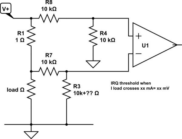
Since LM358 are design for single supply with PNP inputs, they sense to Vee very well. So move Current sensor to Gnd and it will work but not very well as a linear device but for logic levels, simply choose the threshold with some 10% hysteresis.

I would suggest 50~100mV drop @ Imax and then choose threshold for logic level desired. Or use an RRIO OP Amp.

schematic

simulate this circuit – Schematic created using CircuitLab

\$\endgroup\$
3
  • \$\begingroup\$ I can't move the current sense to ground, as I have only access to the high side. \$\endgroup\$ Commented May 6, 2018 at 11:42
  • \$\begingroup\$ I can't move the current sense to ground, as I have only access to the high side - that the LM358 has a voltage swing from 3.5V to 5mV. So that should be fine. What am I missing here with the high side current sensing? \$\endgroup\$ Commented May 6, 2018 at 11:48
  • \$\begingroup\$ You are missing the fact that Vsat to Vcc , Vee rails needs RRO type for linear operation, but if all you want is a comparator, choose the threshold. So R3 goes to 0V not output. and change ratio for IRQ threshold \$\endgroup\$
    – D.A.S.
    Commented May 6, 2018 at 12:38

Your Answer

By clicking “Post Your Answer”, you agree to our terms of service and acknowledge you have read our privacy policy.

Not the answer you're looking for? Browse other questions tagged or ask your own question.