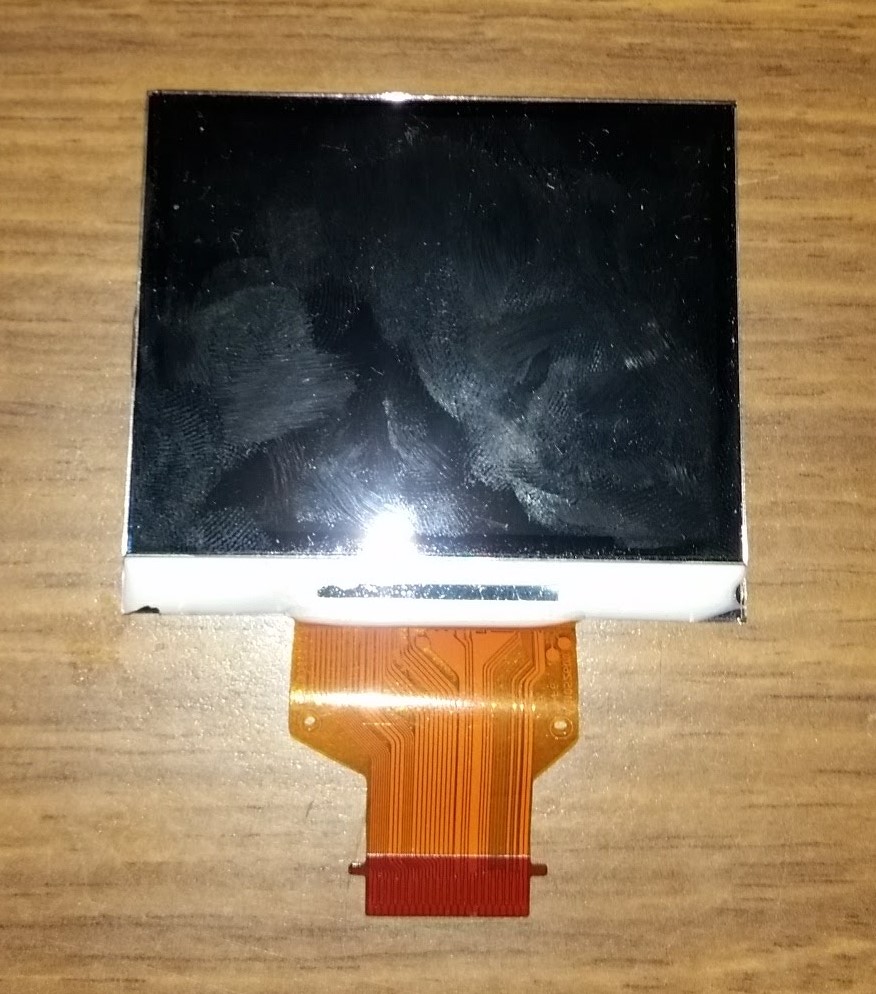
Well there are some things that may be deduced from the two pics you provided. What follows is just what I think about your module and it would be amazing if it was true. Do not take it as correct.
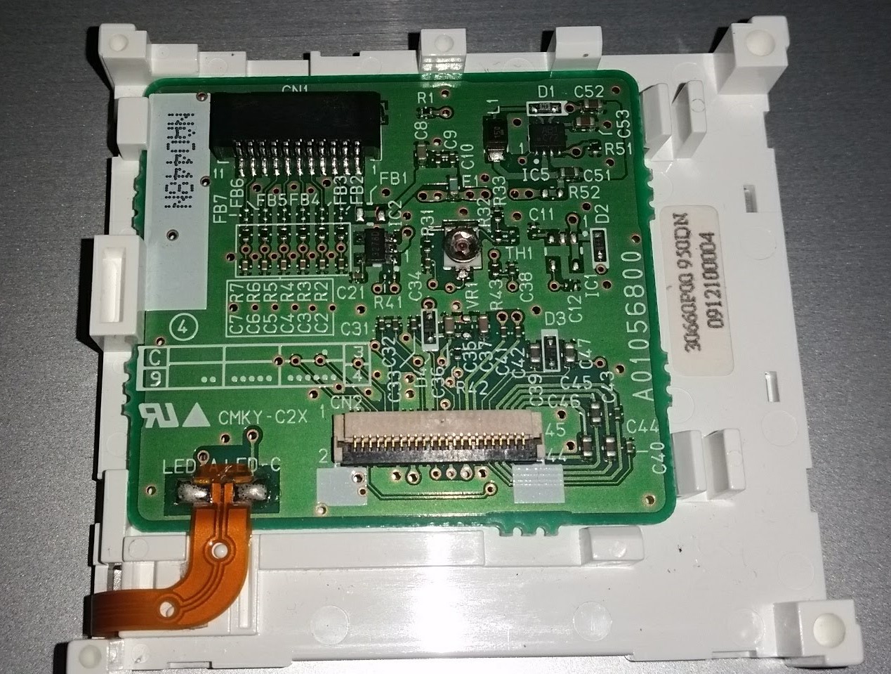
Let's focus on your CN1 connector, the black one. Since this screen needs to be driven by something apart, I would say that connector is the interface to be connect with a microcontroler.
Let's focus on the tracks connected to the back of the CN1 connector (soldered) :
- PIN 1 & 2 : Probably the power supply of the module (VCC). I say that because of the apparent tracks width and because of what comes next.
- PIN 4, 9 & 11 : This is GND since the copper connected covers the most of the PCB surface (it is common).
- PIN 3, 5, 6, 7, 8 & 10 : Those are signals (see how the tracks width is much thinner than the power supply ones).
Two main questions comes to the mind :
- What is the power supply voltage to be used ?
- What is the protocol used to drive the LCD ?
For the first question, well, generally the voltage used to drive this kind of LCD screen is either 3.3V or 5V. You can try first 3.3V to see if the backlight lights up. If not, try 5V. But be careful ! Maybe one of the signal track is used to enable the backlight (so it won't work even with the proper voltage applied if the backlight enable is not driven correctly).
For the second question... I would bet on SPI interface. Why ? Well, first of all, when it comes to drive a LCD screen with this size, SPI interface can be used. Moreover, there are 6 tracks used as signals type. If this is indeed SPI, 4 tracks are used :
- Chip Select ;
- MISO ;
- MOSI ;
- CLK.
This let us 2 signals left.
I have read some datasheets of SPI LCD screen, it is common to find a RESET pin. So, since I am a good player, I'll bet on a RESET signal for the LCD.
1 signal left. I don't really know what it could be used for. Maybe a Backlight Enable command as stated previously ? To be sure, It would be useful to test this screen on the printer to see if it was possible to turn on/off the LCD or to dim it.
Now is the following issue : let's assume it is the correct interface (SPI). Which PIN number is associated with what function ? I have no idea and that's where you will be stuck from. Actually, and this is just an assumption, but since PIN 5, 6, 7 & 8 are routed together (not separated by ground plane like it is for PIN 3 & 10), I would say it is the SPI interface. PIN 3 is either the RESET command or Backlight Enable (if Backlight Enable command there is). Now that we are quite sure about the power supply tracks, you can still try to switch HIGH/LOW some signal traces in the first place to see what happens. But as I said before : Be careful
In any cases, without the datasheet it will be very very difficult to display something. You can still reverse the PCB routing. Will it be useful ? I don't really know.


