0
\$\begingroup\$

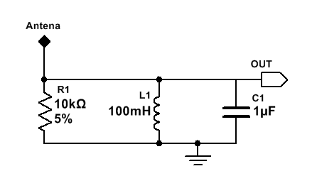
Hello I have just build colpitts oscillator, which gave me perfect 500Hz sinusoidal wave. So far so good. Now I would like to receive this wave in second circuit "receiver" and here problems start. I try to employ parallel RLC oscilator hopping that incoming wave wil resonate and produce output voltage across R. Here is the schematic of receiver:

enter image description here

Values were taken to receive 500Hz according to this formula: enter image description here
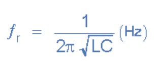
So the resonant frequency is equal to 503 Hz

Scope Output ( Yellow - oscilator output | Blue - received output): enter image description here Problems:
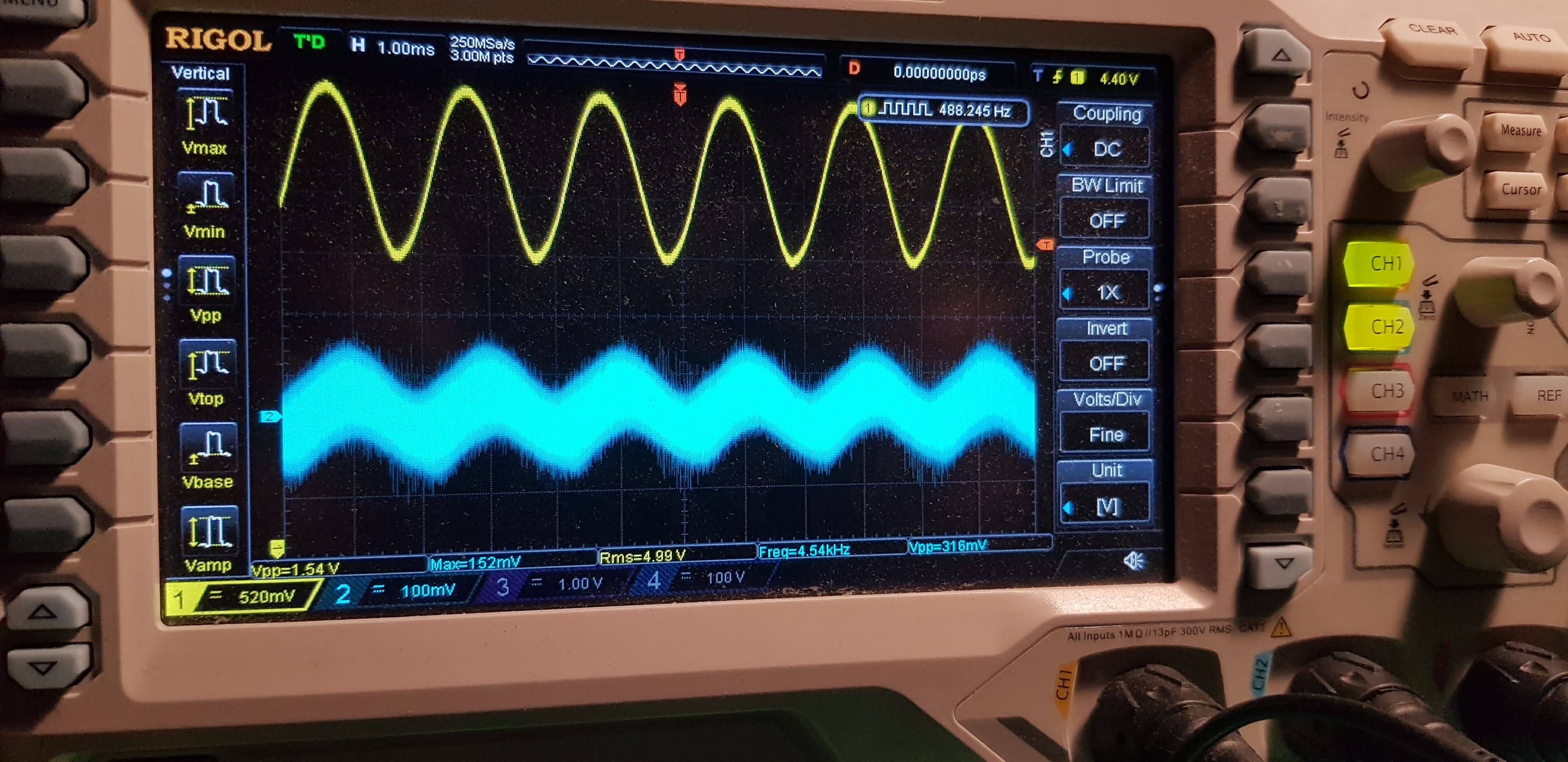
  1. On the scope I monitor the received signal and the good news is, there is some small amplitude, noisy sinusoid. Is it the one I wish to receive? I think it is but I am not 100% sure. The freq on scope jumps back and forth from houdrends of hertz to kilohertz. On the flip side hovewer when I turn of osilator the received sin is also gone. So to summarise how to be sure that I received intened signal?
  2. As you can see received signal is small in amplitude and quite noisy. My goal is to clean it and amplify. Any suggestion in this regard, so I can drive a speak for example?
  3. The received signal (blue one on scope) seems to be a little bit out of phase. Is that normal?
  4. Assuming everything is fine and I receive correct signal, how can I calculate what is the range of my oscillator/transmitter. Any reference, text will be appreciated.

UPDATE:

Input impedance calculations for 500hz input signal:

Resistor -> 10k Ohm

Capacitor -> \$\ \frac{-j}{\omega c} = 7*10^-4j\$

Inductor -> \$\ j \omega c = 314 j\$

So the total inpedance -> \$\ \frac{1}{\frac{1}{R} + \frac{1}{Xc} + \frac{1}{Xl}} = 4,89 * 10^{-10} + 7*10^{-4}i\$

Thanks for help :)

\$\endgroup\$

1 Answer 1

2
\$\begingroup\$

At 500 Hz, a monopole antenna will need to be 150 km long to be able use it effectively as a standard antenna. So your antenna is "short". I don't need to guess because I know you won't have made your antenna 150 km long.

With a "very short" antenna it presents an impedance to the tuned circuit that is capacitive with very high impedance (possibly mega ohms at 500 Hz) therefore the 10k resistor you have used will form a potential divider that virtually kills your signal. However, if you remove the resistor you will have a massively high Q and may not easily tune it plus there will be losses in the inductor that still mean you have massive attenuation.

If you are using a similar antenna to transmit the 500 Hz then trying to drive any signal into it becomes massively problematic because of the high impedance it presents.

Give your self a chance of making this work and adjust your oscillator to produce 1 MHz and forget about trying to make any monopole antenna that will work at 500 Hz. If you need to transmit audio a simple diode and output filter can modulate AM so you can pick it up on an AM receiver.

In the near field you can get capacitive coupling but you'll need a return path for the current and I think this defeats the object of what you are trying to do.

\$\endgroup\$
7
  • \$\begingroup\$ Thanks for suggestions. How did you calculated that 150Km? 3*10^8/500 = 600 000m not 150 000? Also, the input impedance is 4,9*10^-10 + j7*10^-4 which is very very small..or maybe my calc are wrong here? \$\endgroup\$
    – DannyS
    Commented Feb 28, 2018 at 21:38
  • \$\begingroup\$ A monopole is a quarter that length for optimum ohmic impedance. \$\endgroup\$
    – Andy aka
    Commented Feb 28, 2018 at 21:48
  • \$\begingroup\$ Your calcs have to be wrong else every short bit of wire in the universe would look like a short circuit. \$\endgroup\$
    – Andy aka
    Commented Feb 28, 2018 at 21:49
  • \$\begingroup\$ I have updated my original question with calculation of input impedance. Could you please review it since you think it is wrong. Thanks :) \$\endgroup\$
    – DannyS
    Commented Mar 3, 2018 at 20:41
  • \$\begingroup\$ Oh you meant the circuit components. I thought you meant the antenna. However, the impedance of an LC tuned circuit involves much more plus you said it was tuned to 500 Hz so the net impedance would be 10 kohm with the L and C forming a parallel impedance of infinity. \$\endgroup\$
    – Andy aka
    Commented Mar 3, 2018 at 21:16

Your Answer

By clicking “Post Your Answer”, you agree to our terms of service and acknowledge you have read our privacy policy.

Not the answer you're looking for? Browse other questions tagged or ask your own question.