1
\$\begingroup\$

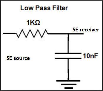
I want to use anti-aliasing filters in different scenarios. Below is the topology for how to use a passive LP filter in the case of a single ended transducer and single ended data acquisition:

enter image description here

How should the RC the connection be:

1-) If the source is diff ended and the data acq. is also diff ended?

2-) If the source is single ended and the data acq. is diff ended?

Could you illustrate these two cases by drawing like mine above.

Edit regarding an answer:

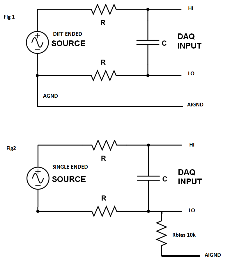
enter image description here

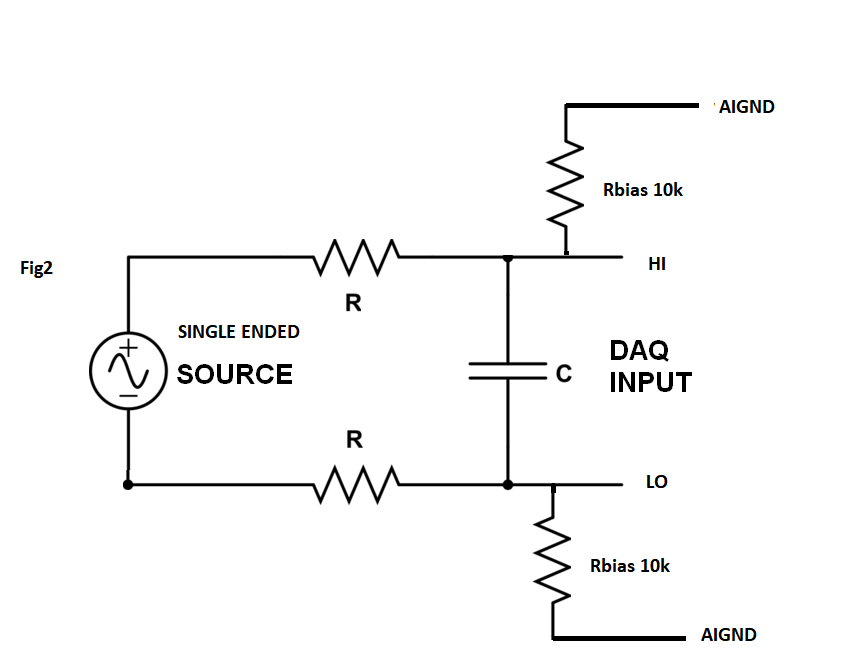
enter image description here

\$\endgroup\$

2 Answers 2

1
\$\begingroup\$

If the source is diff ended and the data acq. is also diff ended?

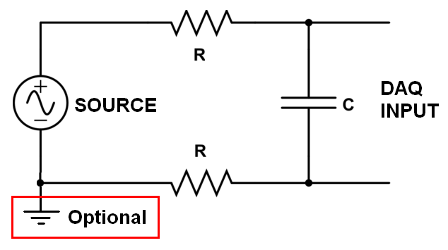
If the DAQ input is differential then you need to attenuate the differential signal at higher frequencies so, use resistors in series with each input and a capacitor directly across the DAQ input after the resistors.

If the source is single ended and the data acq. is diff ended?

You do exactly the same because you don't want to imbalance the impedance of lines that could pick up external inteference (common-mode) and, due to those impedance imbalances, convert a common mode interference to a differential interference.

enter image description here

You might also need to consider impedance balancing at the source and cabling between source and DAQ. You might also need common mode decoupling capacitors to help reduce noise. This is for noise reduction rather than anti-alias filtering.

\$\endgroup\$
11
  • \$\begingroup\$ Thanks I need to be more clear about it. So I drew your circuit in a way with all wrings explicit. It is in my edit or here: i.sstatic.net/Lj7sa.png Now In Fig 1 for DE to DE I guess it is correct? How about Fig 2? I have to use Rbias for commonmode voltage problems for floating SE to DE wirings. Is Fig 2 also correct? \$\endgroup\$
    – user1999
    Commented Feb 27, 2018 at 13:22
  • \$\begingroup\$ I would use AIGND feeding two resistors; one to DAQ+ and one to DAQ-. Value depends on DAQ but 10 kohm to 1 Mohm should work. It will work for either set up. Beware of ground loops as per your fig1. \$\endgroup\$
    – Andy aka
    Commented Feb 27, 2018 at 13:25
  • \$\begingroup\$ Do you mean this: i.sstatic.net/X4gDU.png ?? \$\endgroup\$
    – user1999
    Commented Feb 27, 2018 at 13:30
  • \$\begingroup\$ Yes I do. It works for both. I might be tempted to put 1 nF capacitors in parallel with those 10k resistors to help reduce the impact of common mode noises picked up on the line. Depending on your signal bandwidth and potential interference the capacitors could be uF in value. \$\endgroup\$
    – Andy aka
    Commented Feb 27, 2018 at 13:31
  • \$\begingroup\$ And does the cut of of the LP same formula ? 1/(2*piRC)? Need know it for anti-aliasing filter. \$\endgroup\$
    – user1999
    Commented Feb 27, 2018 at 13:33
2
\$\begingroup\$

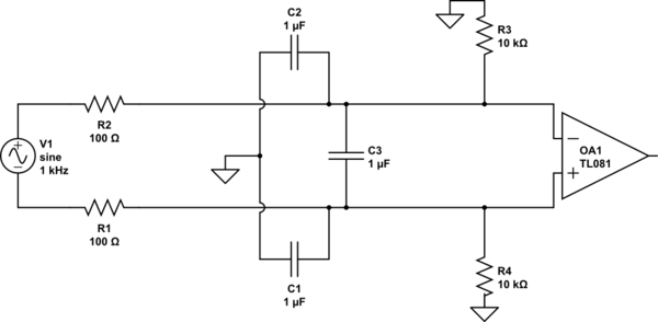
This circuit is even more robust against both differential and against common mode trash

schematic

simulate this circuit – Schematic created using CircuitLab

Please notice C1 and C2 share a COMMON GROUND. :This is on purpose.

===================== April 2020

If the capacitors or resistors are IMBALANCED, are not of precisely the same value, the rejection of CommonMode energy will be VERY POOR. This means the mis-etching of PCB traces will have some effect. You can simulate this impairment.

Whether you can succeed with inductors will depend on the frequencies of interest and the frequencies to reject; also the matching of the inductors will matter, as matching matters for Rs and Cs. Inductors will be more susceptible to external magnetic fields.

\$\endgroup\$
3
  • \$\begingroup\$ Woow this works much better, I checked in simulation. With this one I can even use R3 and R4 bias resistors bigger like 100k and load the source less and get rid of common mode. C3 is setting the LP filter cut off together with 100 Ohm resistors I guess. \$\endgroup\$
    – user1999
    Commented Feb 27, 2018 at 16:25
  • \$\begingroup\$ Do you think adding a 10nF between the source terminals have a good effect for high frequency noise as well? \$\endgroup\$
    – user1999
    Commented Feb 27, 2018 at 16:27
  • \$\begingroup\$ Can I use inductors instead of 100 Ohms(LC lowpass filter)? I was thinking I would even reduce the voltage divider effect coming from 100 Ohms. Does it make sense? \$\endgroup\$
    – user1999
    Commented Feb 27, 2018 at 19:39

Your Answer

By clicking “Post Your Answer”, you agree to our terms of service and acknowledge you have read our privacy policy.

Not the answer you're looking for? Browse other questions tagged or ask your own question.