I'm new to electronics.
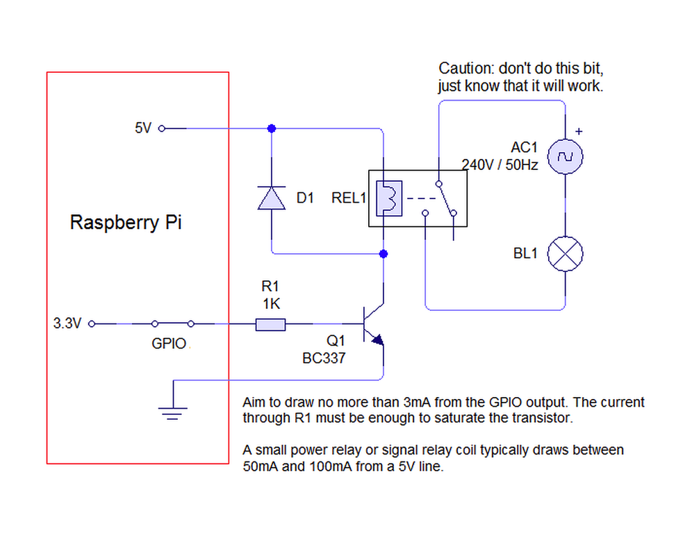
I found the tutorial about the control of a relay using GPIO in raspberry pi from http://arnholm.org/raspberry-pi-controlling-a-relay/ . It has the following electric circuit :
I wonder the existence of the diode laid down parallel with relay. I searched about this and got the answer from Why is there a diode connected in parallel to a relay coil?
Since an inductor (the relay coil) cannot change it's current instantly, the flyback diode provides a path for the current when the coil is switched off. Otherwise, a voltage spike will occur causing arcing on switch contacts or possibly destroying switching transistors.
It says eventually when the switch is off, the flow of relay current should go through the flyback diode to prevent destroying the switching transistor because it causes the undesirable spark on it.
But I am worried about if the relay current from REL1 go through D1 diode, the sudden excess of current might make the pi die after the current going up above the diode.
So I thought one of the solution is if we put 2 diodes in the position D1 and draw a line between them, we can release the current safely.
So my question is
What if we put a resistor above the D1 diode? Does the current can be attenuated with dissipation in the resistor? Can this be also a solution?


voltage spike will occur causing arcing on switch contacts.... it does not refer to the relay contacts in your diagram ... if you used a smaller relay, instead of the transistor, to drive the main relay, then the note about arcing would refer to the contacts of the smaller relay ... arcing would happen because of the inductive load of the bigger relay coil \$\endgroup\$